ZR36067 データシートの表示(PDF) - Unspecified
部品番号
コンポーネント説明
一致するリスト
ZR36067 Datasheet PDF : 48 Pages
| |||
AV PCI CONTROLLER
Table 7: 24-bit Unpacked Pixel Format
Endian-ness
Little Endian
Gib Endian
31...24
0x0
B7...0
Bits
23...16
15...8
R7...0
G7...0
G7...0
R7...0
7...0
B7...0
0x0
In the 24-bit packed format the first active pixel in a line is always
packed as indicated in the “First” row of Table 8. From then on
the byte organization is as described by the table.
Table 8: 24-bit Packed Pixel Format
Bus Cycle
First
Second
Third
31...24
B17...0
G27...0
R37...0
Bits
23...16
15...8
R07...0 G07...0
B27...0 R17...0
G37...0 B37...0
7...0
B07...0
G17...0
R27...0
8.0 GRAPHICS OVERLAY
The ZR36067’s Video DMA Controller is capable of masking off
(i.e., not transmitting) pixels that are marked by ‘0’ in a masking
map prepared and maintained by the driver software. The
masking feature, referred to as overlay or clipping, is turned on
by setting the OvlEnable parameter to ‘1’. As long as OvlEna-
ble=’0’, all pixels within the selected portion of the image are
transferred to destination. The masking map is a one bit deep
map of the video rectangle. Its location in system memory is
defined by a pair of base addresses (one for each field - Mask-
TopBase, MaskBotBase), and an inter-line stride (MaskStride).
The width of the map must be doubleword aligned. Thus, the line
size is:
int((VidWinWid+31) >> 5)
and the number of lines in the map is:
2*VidWinHt, if DispMod==0, or VidWinHt, if DispMod==1.
In order to match the 0/1 values of the map to their correspond-
ing pixels in the video rectangle, the map must follow the format
given in Table 9.
Table 9: Bit, Byte and Doubleword Organization of
the Masking Map
DWORD
...1
0
Byte
...0
3
2
1
0
Bit
7....0 31...24 23...16 15... 8 7...0
Pixel index in line 39...32 31...24 23...16 15...8 7...0
9.0 JPEG CODE TRANSFER
The data flow direction depends on the JPEG mode of opera-
tion. In Motion Video and Still Image Compression, the code is
transferred from the CODE bus to the system memory. In Motion
Video and Still Image Decompression, the code is transferred
from the system memory to the CODE bus.
The compressed data in system memory is structured within
code buffers. Each code buffer may contain a compressed field
or frame (two fields) as specified by a user-configurable bit.
The ZR36067 supports four code buffers, defined dynamically in
a dedicated table, the Code Buffer Table, in the system memory.
Before starting a new JPEG process, the host must load the
physical address of the code buffer table into the
I_STAT_COM_PTR register of the ZR36067.
The actual memory allocated to each code buffer by the operat-
ing system may be fragmented. The content of each entry in the
code buffer table is a pointer to a secondary Fragment Table.
The fragment table contains the pointers to the allocated
memory chunks.
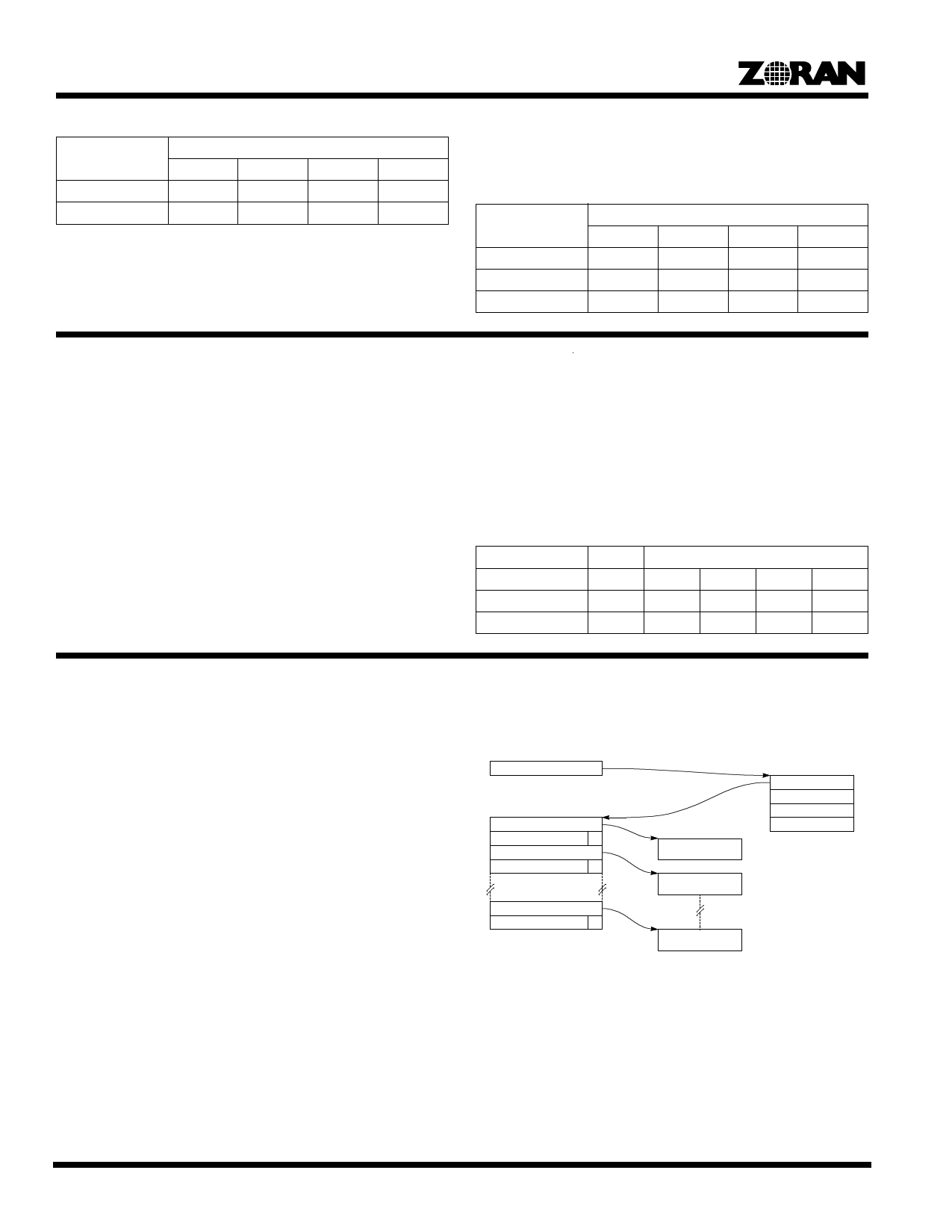
Figure 9 provides a graphical description of the data structure in
the system memory.
I_STAT_COM_PTR
Fragment Table
ADDRESS_0
LENGTH_0
F
ADDRESS_1
LENGTH_1
F
ADDRESS_n-1
LENGTH_n-1
F
F=Final
Fragment_0
Fragment_1
Code Buffer Table
STAT_COM0
STAT_COM1
STAT_COM2
STAT_COM3
Fragment_n-1
Figure 9. JPEG Code Data Structure In System Memory
9.1 The Code Buffer Table
The Code Buffer Table consists of four STAT_COM (“status or
command”) entries, one for each code buffer. The interpretation
of each STAT_COM entry is determined by its l.s. bit, the
STAT_BIT. If STAT_BIT=’0’, the content of the entry is the “com-
20
Share Link: 