ZR36067 データシートの表示(PDF) - Unspecified
部品番号
コンポーネント説明
一致するリスト
ZR36067 Datasheet PDF : 48 Pages
| |||
AV PCI CONTROLLER
7.0 VIDEO OUTPUT CONTROL
The ZR36067 outputs the video pixels over the PCI bus, using
DMA bursts, initiated and controlled by the ZR36067’s Video
DMA Controller. In order to enable the DMA Controller, the
Master Enable bit of the PCI configuration space must be set to
‘1’, and the VidEn bit in the Video Display Configuration Register
must also be set to ‘1’. Once VidEn==’1’, the software is not
allowed to change registered parameters that are involved in the
video processing. The register description (See “Application-
Specific Registers (ASRs)” on page 25) specifies the conditions
under which each parameter is allowed to be modified.
The ZR36067 transfers the video to a rectangle in the display (or
system) memory, defined by a base address for each field
(MaskTopBase, MaskBotBase), an inter-line stride (DispStride),
and the rectangle height (VidWinHt) and width (VidWinWid).
Obviously, these parameters must be provided by the host prior
to enabling the Video DMA Controller.
7.1 Display Modes
The ZR36067 can either display both fields, emulating the inter-
laced input, or only the top field. The latter option has the
advantage of reducing the motion artifacts that might be exhibit-
ed when interlaced video is displayed on a non-interlaced
monitor. The parameter that controls the display mode is
DispMod.
By a proper configuration of the display base addresses it is also
possible to display two fields (from either one or two separate
video sources) on two separate rectangles (video windows).
7.2 Frame Grabbing
The ZR36067 has a special mode for capturing video frames (or
fields) and storing them in system memory. This mode is invoked
by setting the SnapShot parameter to ‘1’. When in this mode,
every time the host switches the FrameGrab bit from ‘0’ to ‘1’, the
ZR36067 downloads a frame (or a field, if DispMod==1), to
memory.
Following is an example of a flow of actions intended to grab one
frame. The example assumes that the vertical sync is used as an
interrupt source (by externally tying VSYNC to GIRQ0 or
GIRQ1), and that prior to grabbing the frame, the ZR36067
operates in the “normal” continuous scheme of live video
display.
• Through a push-button click in the application GUI the user
triggers a frame grabbing request.
• The host sets SnapShot=1. The ZR36067’s Video DMA
Controller waits for the next VSYNC and then freezes the
live display. Since now SnapShot=1 and FramGrab=0, video
parameters can be changed (even without VidEn=0; refer to
section 13.0 “Application-Specific Registers (ASRs)”).
• The host sets new addresses in VidTopBase and VidBot-
Base. These addresses point to main memory. DispStride is
also given a new value. If needed, other video parameters
can be changed now, e.g., pixel format, etc.
• The host sets FrameGrab=1. The ZR36067 waits until the
next VSYNC and then transmits two consecutive fields to
main memory.
• After the second of the two fields is completed, FrameGrab
is cleared by the ZR36067.
• When the host senses (after constant polling or polling in-
side VSYNC-triggered interrupts) that FrameGrab=0 again,
it sets the old addresses back to VidTopBase and VidBot-
Base. DispStride is given back its old value. The remainder
of the previous video parameters can be restored now.
• The host sets SnapShot=0, putting the ZR36067 back into
the continuous video display mode.
• With the next VSYNC the ZR36067’s Video DMA Controller
resumes “normal” live display operation.
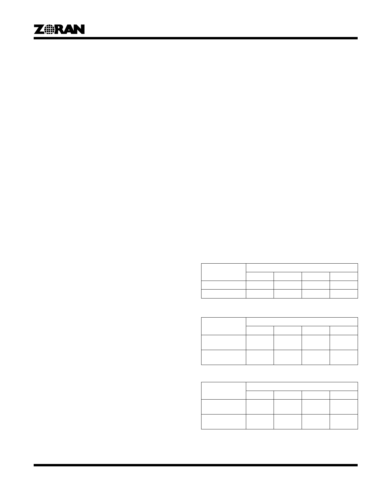
7.3 Output Pixel Organization
The output pixel format is determined by the following parame-
ters: YUV2RGB, Pack24 (applicable only to RGB 8,8,8 format),
and LittleEndian (applicable to all formats, excluding the 24-bit
packed). Following are the bit organizations of the different pixel
formats when a video doubleword is transferred over the PCI
bus:
Table 4: YUV 4:2:2 Pixel Format
Endian-ness
Little Endian
Gib Endian
31...24
Y17...0
V07...0
Bits
23...16
15...8
V07...0 Y07...0
Y17...0 U07...0
7...0
U07...0
Y07...0
Table 5: RGB 5,5,5 Pixel Format
Endian-ness
Little Endian
Gib Endian
31...24
0,R14...0,
G14...3
G12...0,
B14...0
Bits
23...16
15...8
G12...0,
B14...0
0,R04...0,
G04...3
0,R14...0, G02...0,
G14...3 B04...0
7...0
G02...0,
B04...0
0,R04...0,
G04...3
Table 6: RGB 5,6,5 Pixel Format
Endian-ness
Little Endian
Gib Endian
31...24
R14...0,
G15...3
G12...0,
B14...0
Bits
23...16
15...8
G12...0,
B14...0
R04...0,
G05...3
R14...0,
G15...3
G02...0,
B04...0
7...0
G02...0,
B04...0
R04...0,
G05...3
19
Share Link: 