ZR36067 データシートの表示(PDF) - Unspecified
部品番号
コンポーネント説明
一致するリスト
ZR36067 Datasheet PDF : 48 Pages
| |||
AV PCI CONTROLLER
5.5.4 Connecting ZR36067 To ZR36060 Host and Code
Interfaces
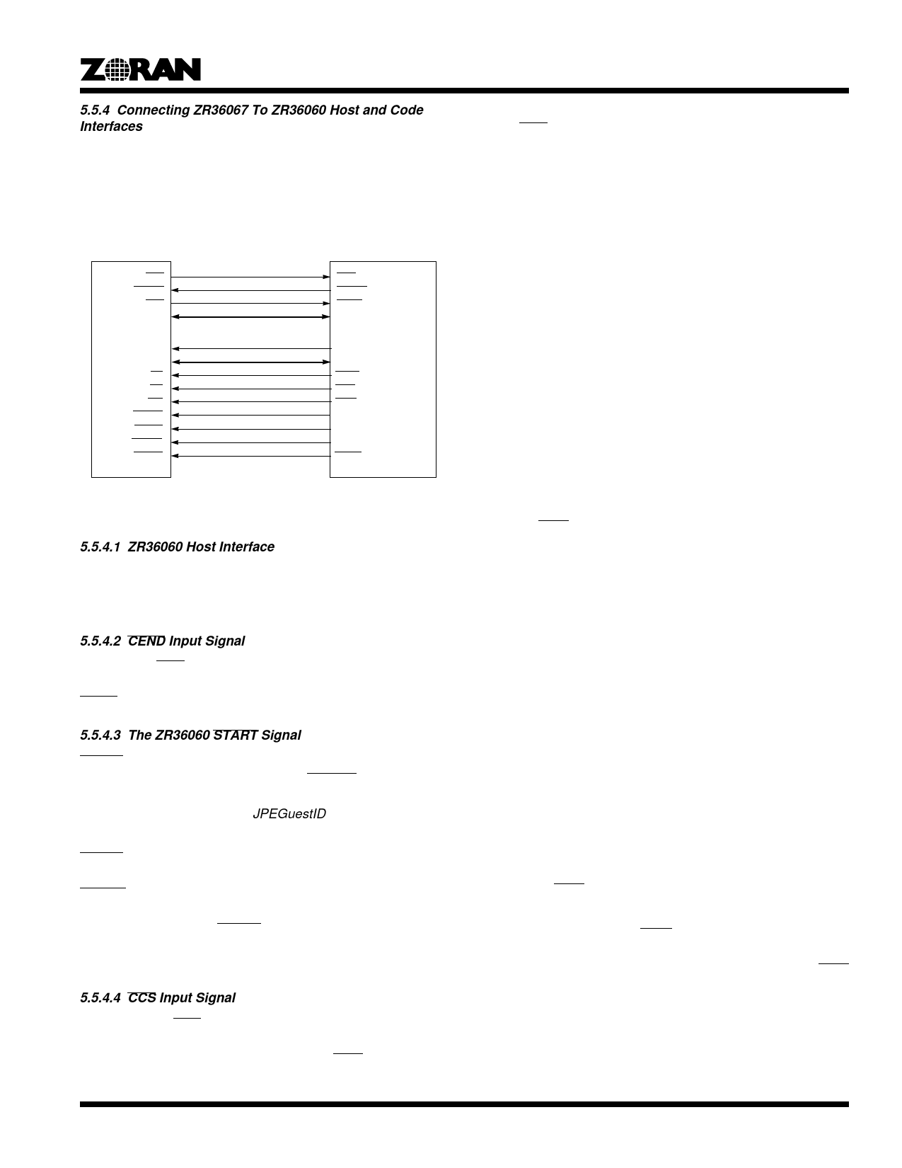
Figure 8 shows the recommended connection of the ZR36067 to
the ZR36060 Host and Code interfaces. For recommended con-
nections between the ZR36067 and the ZR36050 Host and
Code Interfaces, refer to the ZR36057 data sheet.
ZR36060
CCS
CBUSY
END
CODE[7:0]
ADDR[1:0]
DATA[7:0]
CS
RD
WR
RESET
SLEEP
FRAME
START
ZR36067
CCS
CBUSY
CEND
CODE[7:0]
GADR[1:0]
GDAT[7:0]
GCSn
GRD
GWR
GPIOa
GPIOb
GPIOc
GCSm
Figure 8. ZR36067 And ZR36050 Host And Code Interfaces
5.5.4.1 ZR36060 Host Interface
The host interface of the ZR36060 is controlled by the ZR36067
as one of the guests. The recommended guest timing parame-
ters are Tdur=12, Trec=3.
5.5.4.2 CEND Input Signal
Assertion of END by the ZR36050 indicates the end of a field
process in compression or decompression. This is latched as
CEND in the Codec Interface.
5.5.4.3 The ZR36060 START Signal
START signals the ZR36060 to start a compression or decom-
pression process. Activation of START is performed
automatically by the ZR36067, by writing to a guest designated
for this purpose (specified by JPEGuestID).
In Motion Video Compression mode, the first activation of
START is initiated by the host after finishing the initialization of
all the peripheral devices. After completion of the first field,
START is activated by the ZR36067 after the code of the
previous field has been transferred to system memory. In
Decompression mode, START is activated only after the Code
FIFO has been filled from the relevant system memory code
buffer.
5.5.4.4 CCS Input Signal
The ZR36060’s CCS signal designates the start of a code trans-
action. It stays active until the end of the transaction. In
Compression mode, the ZR36067 uses CCS to enable the
sampling of the incoming code stream. In Decompression mode,
it uses CCS to enable the drive of the code stream.
5.6 I2C Bus Interface
The I2C port of the ZR36067 consists of a clock signal, SCK, and
data signal, SDA. Both have two possible levels: active low or
passive tri-state. This configuration lets the ZR36067 be the only
master of an I2C clock. Both lines must be pulled-up externally.
By accessing the I2C application-specific register bits appropri-
ately, the host software can generate valid I2C start and stop
conditions, write address and write or read data one bit at a time.
5.7 General Purpose I/O Pins
The ZR36067 has 8 general purpose I/O pins, fully controlled by
the host. Each of these pins can be separately configured as
input or output. When configured as an output, the host is able
to force the level of a pin through its corresponding register bit.
5.8 Interrupt Requests
The ZR36067’s interrupt manager connects to the various con-
ditions that may generate an interrupt request, enables or
disables them as specified in the Interrupt Control Register, and
drives the INTA output. It stores the corresponding status bits in
the Interrupt Status Register, and clears the status bits per host
instructions.
The ZR36067 can associate any one of the following events with
an interrupt request:
• A positive edge on the GIRQ1 input pin.
• A positive edge on the GIRQ0 input pin.
• MPEG mode - the code memory buffer pointer passing one
of its report points.
• JPEG modes - successful completion of a JPEG field or
frame process (in compression or decompression).
Each of these events can be separately enabled or disabled
through the corresponding bit in the Interrupt Control Register.
An additional global enable bit enables or disables all interrupts.
When an interrupt-associated event occurs, two things happen:
• The corresponding bit in the Interrupt Status Register is set.
• If the interrupt is enabled, and the interrupts are enabled glo-
bally, the INTA open-drain output pin is asserted to its
active-low level.
Both the status bit(s) and INTA remain active, until the host
clears those status bits that are currently set. This is done by
writing a ‘1’ to those bits. When the host does that, the INTA
output signal returns to its passive, tri-state level.
If the host attempts to clear any of the Interrupt Status Register
bits at the same time that the interrupt logic attempts to set it
(because of an interrupt event), the set operation has priority
over the clear operation.
17
Share Link: 