ZR36067 データシートの表示(PDF) - Unspecified
部品番号
コンポーネント説明
一致するリスト
ZR36067 Datasheet PDF : 48 Pages
| |||
AV PCI CONTROLLER
The ZR36067 Video Interface drives out the video synchroniza-
tion signals synchronized with the negative edge of VCLKx2
(every other edge). The VCLK input is used as a phase qualifier.
The timing of the rising and the falling edges of VSYNC with
respect to the HSYNC signal are:
• Odd fields - The edges of VSYNC occur in the middle of the
non-active portion of HSYNC.
• Even fields - The edges of VSYNC occur in the middle of the
active portion of HSYNC.
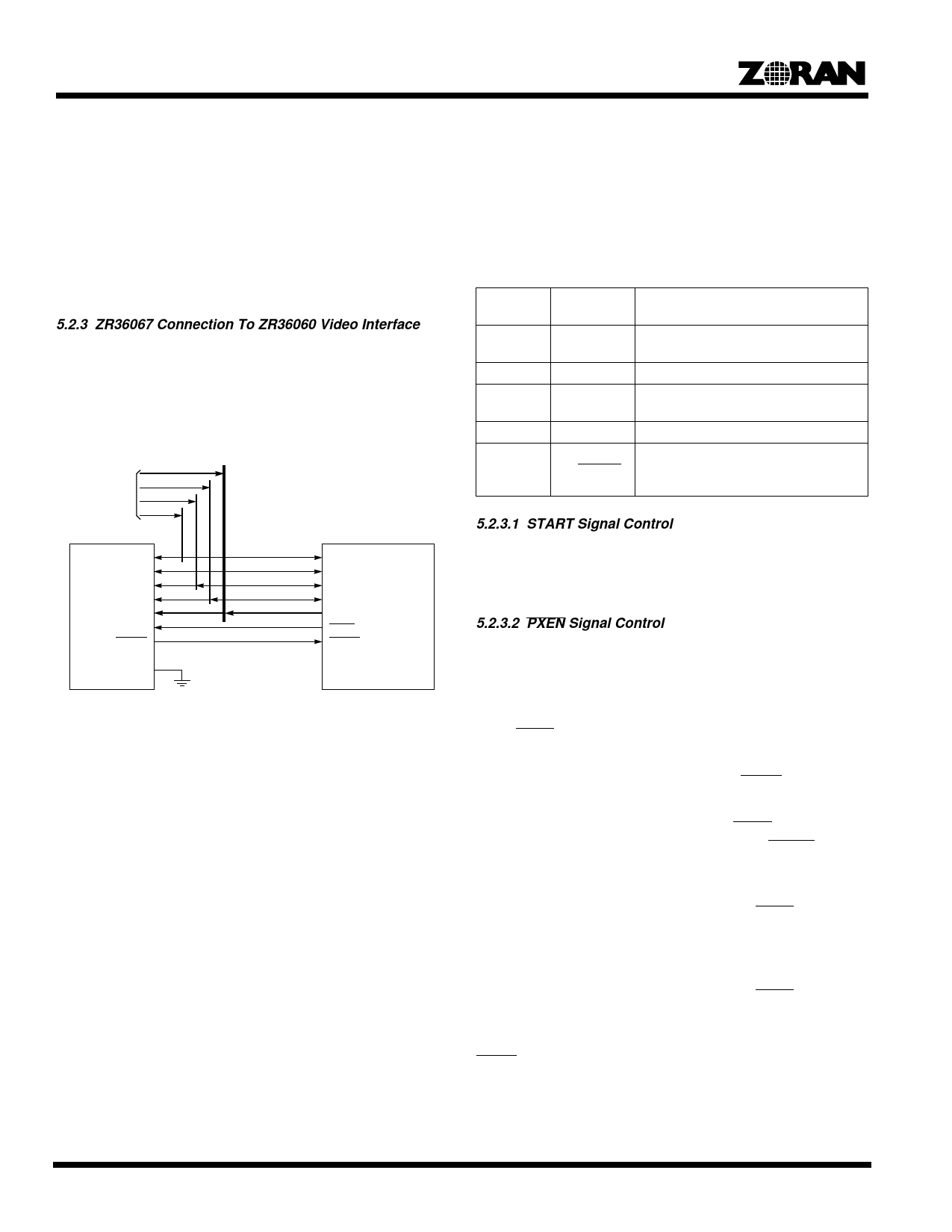
5.2.3 ZR36067 Connection To ZR36060 Video Interface
Figure 3 shows the recommended connections between the
ZR36067 and the ZR36060 Video Interface. For recommended
connections between the ZR36067 and the ZR36016 Video
Interface, refer to the ZR36057 data sheet.
From External
Video Source
ZR36060
VCLK
VCLKx2
VSYNC
HSYNC
YUV[15:0]
PVALID
RTBSY
POE
ZR36067
VCLK
VCLKx2
VSYNC
HSYNC
YUV[15:0]/RGB[23:0]
PXEN
RTBSY
Figure 3. Recommended Connection of ZR36067 to
ZR36060 Video Interface
In Motion Video Compression, the YUV video and synchroniza-
tion signals are driven by the external video source (for example,
a SAA7110) to the inputs of the ZR36067 and ZR36060.
In Motion Video Decompression, the synchronization signals are
driven by the ZR36067 (in sync master mode) or by an external
sync generator, associated with the video source. The decom-
pressed digital video is transferred from the ZR36060 video bus
to the ZR36067 video interface. The video bus of the external
video source, and if necessary its sync signals, must be forced
to float, typically using software control.
In Still Image Compression, the video bus as well as the sync
signals are driven by the ZR36067. Therefore, the video bus of
the external video source (such as the video decoder of
Figure 1), and if necessary its sync signals, must be forced to
float.
In Still Image Decompression mode, the sync signals are driven
by the ZR36067. Decompressed video is transferred from the
ZR36060 to the ZR36067’s Video Interface. In this mode of
operation, the video bus and sync signals of an external video
source (such as the video decoder of Figure 1) must be forced
to float.
Table 3 defines the ZR36060 and ZR36067 parameters which
define the portion of the field to be processed (the active
portion).
Table 3: Parameters Defining The Active Portion Of A
Field
ZR36067 ZR36060
Parameter Parameter
Meaning
NAX
HStart
The number of pixels to be skipped,
counted from the active edge of HSYNC.
PAX
HEnd-HStart The number of active pixels in a line.
NAY
VStart
The number of lines to be skipped
counted from the active edge of VSYNC.
PAY
VEnd-VStart The number of active lines in a field.
Odd_Even FIDet with
the FRAME
signal
5.2.3.1 START Signal Control
The START Signal is used with the ZR36016 only, to start the
Compression/Decompression process at the correct time for the
desired field type.
5.2.3.2 PXEN Signal Control
The ZR36067 drives the PVALID input of the ZR36060. While
PVALID is deactivated, the ZR36060 does not sample the video
bus and the video sync inputs.
To keep the ZR36067 and the ZR36060 synchronized, deactiva-
tion of PXEN by the ZR36067 also ‘holds’ the horizontal counting
and processing inside the ZR36067.
In Motion Video Compression mode, PXEN is activated
continuously.
In Motion Video Decompression mode, PXEN is asserted by
then ZR36067 after latching the rising edge of RTBSY, indicat-
ing that the first strip is ready in the ZR36060 strip memory.
In Still Image Compression mode, the image is transferred to the
ZR36067 by the host software pixel by pixel. PXEN is activated
only when a pixel is ready to be sent out from the ZR36067
Video Interface to the ZR36060 video input.
In Still Image Decompression mode, the image is read from the
ZR36067 by the host software pixel by pixel. PXEN is activated
to get the next pixel from the ZR36060 only after the previous
pixel has been read by the host.
PXEN can be de-asserted dynamically (in the middle of a
process) in response to several different conditions. The
dynamic de-assertion is enabled independently by three config-
uration bits - VFIFO_FB, CFIFO_FB, RTBSY_FB. The host
12
Share Link: 