ZR36067 データシートの表示(PDF) - Unspecified
部品番号
コンポーネント説明
一致するリスト
ZR36067 Datasheet PDF : 48 Pages
| |||
AV PCI CONTROLLER
• The host writes a full doubleword to the PostOffice register,
containing the guest’s identity (0,..,7), the specific guest reg-
ister (0,...,7), and an indication that this is a read request
(direction bit = 0). The data portion of the doubleword is
meaningless, but should be set to a byte of zeros. As a result
of writing to the PostOffice data byte, the PostOffice pending
bit is set to ‘1’.
• The ZR36067 completes the current code-write cycle, if one
is being executed, and before executing the next code-write
cycle (if one is needed), it executes the pending PostOffice
request. It transfers the byte read from the guest to bits 7...0
of the PostOffice register. At the completion of the GuestBus
read cycle it clears the request pending bit.
• The host may read the PostOffice register, to verify that the
pending bit is ‘0’, meaning that the read request has been
completed and the data portion of the PostOffice register is
the result.
• Note that in multiple (back-to-back) PostOffice operations
the host has to poll the request pending bit only once be-
tween two requests, since reading this bit zero indicates
both that the previous request has been completed and that
the next request can be made.
5.5 Codec Bus Interface
The Codec Front End (CFE) interfaces to the ZR36060 or
ZR36050 JPEG Codec to transfer code (compressed data) to or
from the ZR36067. The CFE is designed to operate with the
ZR36060 or ZR36050 configured in Code Bus Master mode. In
Compression mode, the CFE receives the code stream from the
codec and transfers it to the Code FIFO. In Decompression
mode, the CFE transfers the code stream from the Code FIFO
to the codec in response to the codec’s read requests.
The CFE uses the CODE[7..0] bus to transfer the code using the
handshaking signals CCS and CBUSY, synchronized to
VCLKx2. The ZR36067 supports the highest ZR36060 and
ZR36050 code bus transfer rate, one clock cycle per CODE bus
cycle.
5.5.1 Compression Mode Code Transactions
The functional timing diagram for compression is shown in
Figure 5.
In this example, two code bytes are transferred from the
ZR36060 to the ZR36067. The falling edge of CCS designates
the start of the cycle. The data is driven by the ZR36060 at the
rising edge of VCLKx2. The ZR36067’s Codec Interface
samples the data with VCLKx2 enabled by CCS.
VCLKx2
CCS
CODE[7:0]
(Input)
n
n+1
Figure 5. Compression Mode Code Transactions
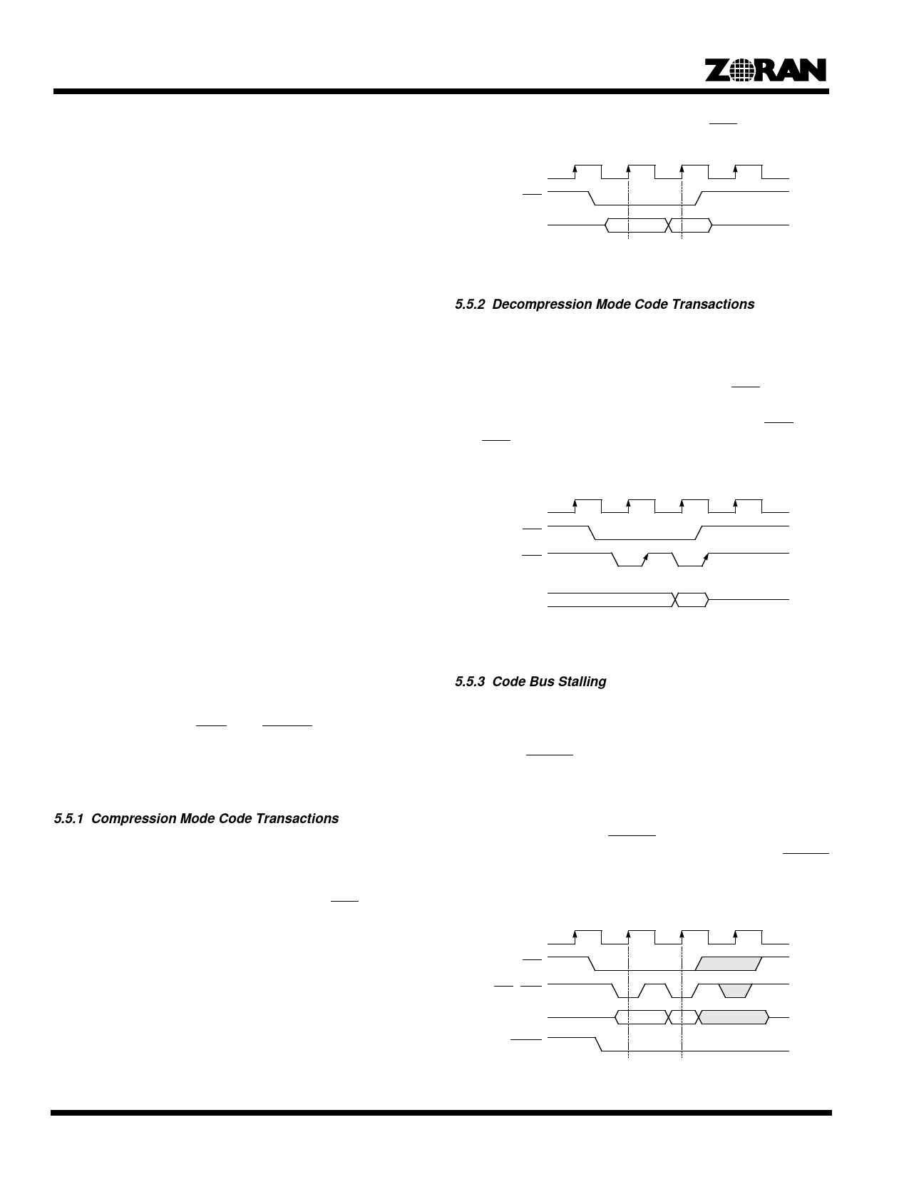
5.5.2 Decompression Mode Code Transactions
The functional timing diagram for decompression is shown in
Figure 6.
In this example, two code bytes are transferred from the
ZR36067 to the ZR36060. The falling edge of CCS designates
the start of the cycle. The data is driven by the ZR36067. The
ZR36060 samples the data with the rising edge of COE (note
that COE is not an input to the ZR36067; it is mentioned here
only for the completeness of the description).
VCLKx2
CCS
COE
(Not an Input to
the ZR36067)
CODE[7:0]
(Output)
n
n+1
Figure 6. Decompression Mode Code Transactions
5.5.3 Code Bus Stalling
The ZR36060 is the master of the code transactions in Compres-
sion and Decompression modes. Any number of bytes can be
transferred in a contiguous burst. The ZR36067 uses the
ZR36060’s CBUSY signal to stall the CODE bus, in order to
prevent overflow of the Code FIFO in compression or underflow
in decompression. Figure 7 shows the functional timing diagram
for CODE bus stalling.
The ZR36060 examines CBUSY one clock cycle prior to the
beginning of each access cycle. The ZR36067 asserts CBUSY
one VCLKx2 cycle before the beginning of the last desired code
transfer cycle.
VCLKx2
CCS
COE / CWE
CODE[7:0]
CBUSY
This access is blocked.
Figure 7. Code Bus Stalling
16
Share Link: 