VT82C596 データシートの表示(PDF) - Unspecified
部品番号
コンポーネント説明
一致するリスト
VT82C596 Datasheet PDF : 96 Pages
| |||
:H &RQQHFW 7HFKQRORJLHV ,QF
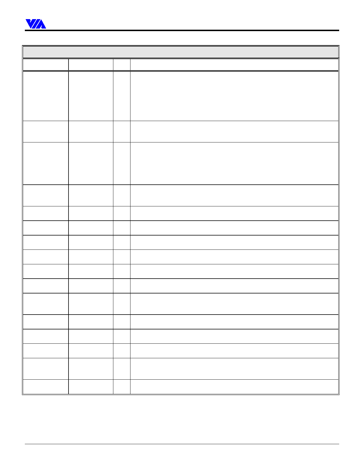
VT82C596B
Signal Name
SA[19:0]
LA[23:17]
SD[15:0]
SBHE#
IOR#
IOW#
MEMR#
MEMW#
SMEMR#
SMEMW#
BALE
IOCS16#
MCS16#
IOCHCK#
IOCHRDY
ZWS#
ISA Bus Interface
Pin #
I/O Signal Description
V4, U4, W5, IO ISA Address Bus
T5, Y6, V6,
Y7, V7, U7,
W8, T8, Y9,
V9, U9, W10,
T10, Y11,
W11, T11, U11
T12, Y13, V13, IO ISA “Latched” Address Bus: The LA[23:17] address lines are bi-directional.
U13, W14,
These address lines allow accesses to physical memory on the ISA bus up to
T14, Y15
16Mbytes.
W19, Y19, IO ISA Bus Data. SD[15:0] provide the data path for devices residing on the ISA bus.
W18, Y18,
V17, Y17, T16,
SD7:4 are strap options for keyboard inputs 6:3 (see Function 0 Rx5A)
W16, V1, T1,
Y2, W2, T2,
U2, W3, V3
W12
IO ISA Byte High Enable. SBHE# indicates, when asserted, that a byte is being
transferred on the upper byte (SD[15:8]) of the data bus. SBHE# is negated during
refresh cycles.
Y5
IO ISA I/O Read. IOR# is the command to an ISA I/O slave device which indicates
that the slave may drive data on to the ISA data bus.
T4
IO ISA I/O Write. IOW# is the command to an ISA I/O slave device which indicates
that the slave may latch data from the ISA data bus.
V15
IO ISA Memory Read. MEMR# is the command to a memory slave which indicates
that it may drive data onto the ISA data bus.
U15
IO ISA Memory Write. MEMW# is the command to a memory slave which indicates
that it may latch data from the ISA data bus.
W4
O ISA Standard Memory Read. SMEMR# is the command to a memory slave,
under 1MB, which indicates that it may drive data onto the ISA data bus
U3
O ISA Standard Memory Write. SMEMW# is the command to a memory slave,
under 1MB, which indicates that it may latch data from the ISA data bus.
U10
O ISA Bus Address Latch Enable. BALE is an active high signal asserted by the
VT82C596B to indicate that the address (SA[19:0], LA[23:17] and the SBHE#
signal) is valid
V12
IO ISA 16-Bit I/O Chip Select. This signal is driven by I/O devices on the ISA Bus to
indicate that they support 16-bit I/O bus cycles.
Y12
IO ISA Memory Chip Select 16. ISA slaves that are 16-bit memory devices drive this
line low to indicate they support 16-bit memory bus cycles.
Y1
I ISA I/O Channel Check. When this signal is asserted, it indicates that a parity or
an uncorrectable error has occurred for a device or memory on the ISA Bus.
T3
IOD ISA I/O Channel Ready. This signal is normally high. Devices on the ISA Bus
assert IOCHRDY low to indicate that additional time (wait states) is required to
complete the cycle.
Y3
I ISA Zero Wait State. Devices on the ISA Bus assert ZWS# to indicate that no wait
states are required.
Revision 0.3 June 17, 1999
-11-
Pinouts
Share Link: 