ZR36067 データシートの表示(PDF) - Unspecified
部品番号
コンポーネント説明
一致するリスト
ZR36067 Datasheet PDF : 48 Pages
| |||
AV PCI CONTROLLER
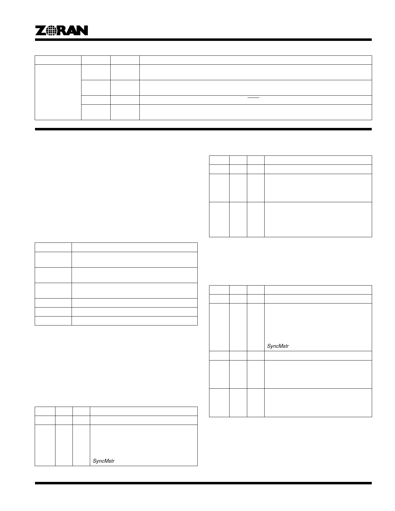
Table 14: ZR36067 PCI Configuration Space Registers
Address Offset
0x3C
Bits
31:24
23:16
15:8
7:0
Type
R
R
R
RW
Description
Max_Lat - Hardwired to 0x10 (i.e., 4 µs). This value indicates for the operating system how often the
device needs access to the PCI bus.
Min_Gnt - Hardwired to 0x2 (i.e., 0.5us). Indicates to the operating system the minimum length of a
burst.
Interrupt pin. Hardwired to 0x1, indicating that INTA is used.
Interrupt Line. These bits indicate the interrupt line that is being used (e.g., IRQ10 => 0xA, etc.).
Default value is 0xA.
13.0 APPLICATION-SPECIFIC REGISTERS (ASRS)
The ZR36067 application-specific registers (ASRs) are memory-
mapped. Their base address is configured by the host into PCI
configuration address 0x10. The ZR36067 claims a contiguous
range of 4K bytes of memory. PCI memory-read accesses to
addresses (within the 4K range) that are not explicitly described
in this section return zeros.
The ASRs can be accessed in any byte combination.
The column Mod of the following tables defines the conditions
under which each parameter of the ASRs is allowed to be
modified by the host software. The following abbreviations are
used:
Address Offset: 0x000 (Continued)
Bit
29:20
19:10
Type
R
RW
Mod
vid
Description
Reserved. Returns zero.
HStart - Horizontal Start Offset. Number of
pixel clocks in a line from the active edge of
HSYNC until the first pixel to be sampled.
Default value is 0x001.
9:0 RW vid HEnd - Horizontal End Offset.
Number of pixel clocks in a line from the
active edge of HSYNC until the last pixel to
be sampled.
Default value is 0x3FF.
Abbreviation
Description
all
This parameter may be modified on the fly, i.e. any
time.
res
This parameter is set once after a reset of the
ZR36067, no modifications allowed during operation.
vid
This parameter may be modified if either VidEn = ‘0’
or SnapShot = ‘1’ and FrameGrab = ‘0’.
cod
This parameter may be modified if CodReadEn = ‘0’.
snap
This parameter may be modified if SnapShot = ‘1’.
jpg
This parameter may be modified if P_reset = ‘0‘.
Note that after a hard or soft reset VidEn = ‘0’, CodReadEn = ‘0’,
and P_reset = ‘1’.
13.1 Video Front End Horizontal Configuration
Register
This 32 bit register contains the horizontal configuration param-
eters of the video source.
Address Offset: 0x000
Bit Type Mod
Description
31
R
Reserved. Returns zero.
30 RW vid HSPol - HSYNC Polarity. HStart and HEnd
are counted from the active edge of HSYNC.
‘1’ - negative edge of HSYNC.
‘0’ - positive edge of HSYNC (default value).
HSPol also determines HSYNC polarity when
SyncMstr=’1’.
13.2 Video Front End Vertical Configuration Register
This 32 bit register contains the vertical configuration parame-
ters of the video source.
Address Offset: 0x004
Bit
31
30
29:20
19:10
9:0
Type
R
RW
R
RW
RW
Mod
vid
vid
vid
Description
Reserved. Returns zero.
VSPol - VSYNC Polarity.
VStart and VEnd are counted from the active
edge of VSYNC.
‘1’ - negative edge of VSYNC.
‘0’ - positive edge of VSYNC (default value).
VSPol also determines VSYNC polarity when
SyncMstr=’1’.
Reserved. Returns zero.
VStart - Vertical Start Offset. Number of lines
from the active edge of VSYNC until the first
line to be sampled.
Default value is 0x001.
VEnd - Vertical End Offset. Number of lines
from the active edge of VSYNC until the last
line to be sampled.
Default value is 0x3FF.
25
Share Link: 