IDT82V2048 データシートの表示(PDF) - Integrated Device Technology
部品番号
コンポーネント説明
一致するリスト
IDT82V2048 Datasheet PDF : 61 Pages
| |||
IDT82V2048 OCTAL T1/E1 SHORT HAUL LINE INTERFACE UNIT
INDUSTRIAL TEMPERATURE RANGES
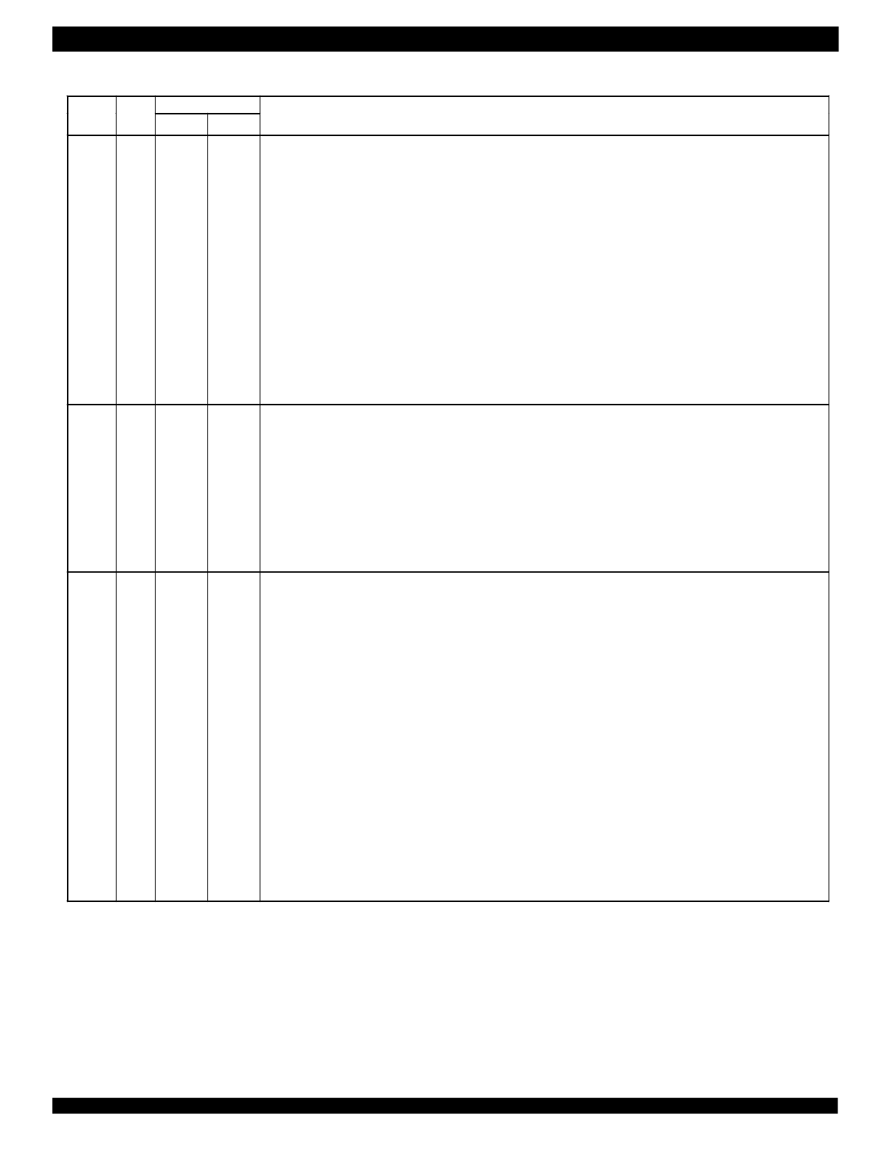
PIN DESCRIPTION (CONTINUED)
Name
Type
Pin No.
QFP144 BGA160
Description
TS2/
I
86
J12 TS2: Template Select 2
SCLK/
In hardware control mode, the signal on this pin is the most significant bit for the transmit template select.
ALE/AS
Refer to Transmit Template of the Functional Description for details.
SCLK: Shift Clock
In serial host mode, the signal on this pin is the shift clock for the serial interface. Data on pin SDO is
clocked out on falling edges of SCLK if pin CLKE is Low, or on rising edges of SCLK if pin CLKE is High.
Data on pin SDI is always sampled on rising edges of SCLK.
ALE: Address Latch Enable
In parallel Intel multiplexed host mode, the address on AD[4:0] is sampled into the device on falling edges
of ALE (signals on AD[7:5] are ignored). In non-multiplexed host mode, ALE should be pulled High.
AS: Address Strobe (Active Low)
In parallel Motorola multiplexed host mode, the address on AD[4:0] is latched into the device on falling
edges of AS (signals on AD[7:5] are ignored). In non-multiplexed host mode, AS should be pulled High.
TS1/RD I
85
J13 TS1: Template Select 1
/R/W
In hardware control mode, the signal on this pin is the second most significant bit for the transmit template
select. Refer to Transmit Template of Functional Description for details.
RD: Read Strobe (Active Low)
In parallel Intel multiplexed or non-multiplexed host mode, this pin is active low for read operation.
R/W: Read/Write Select
In parallel Motorola multiplexed or non-multiplexed host mode, the pin is active low for write operation and
high for read operation.
TS0/ I
84
J14 TS0: Template Select 0
SDI/WR
In hardware control mode, the signal on this pin is the least significant bit for the transmit template select.
/DS
Refer to Transmit Template of Functional Description for details.
SDI: Serial Data Input
In serial host mode, this pin input the data to the serial interface. Data on this pin is sampled on rising
edges of SCLK.
WR: Write Strobe (Active Low)
In parallel Intel host mode, this pin is active low during write operation. The data on D[7:0] (in non-
multiplexed mode) or AD[7:0] (in multiplexed mode) is sampled into the device on rising edges of WR.
DS: Data Strobe (Active Low)
In parallel Motorola host mode, this pin is active low. During a write operation (R/W = 0), the data on D[7:0]
(in non-multiplexed mode) or AD[7:0] (in multiplexed mode) is sampled into the device on rising edges of
DS. During a read operation (R/W = 1), the data is driven to D[7:0] (in non-multiplexed mode) or AD[7:0] (in
multiplexed mode) by the device on rising edges of DS.
In parallel Motorola non-multiplexed host mode, the address information on the 5 bits of address bus A[4:0]
are latched into the device on the falling edge of DS.
8
Share Link: 