ISP1562 データシートの表示(PDF) - NXP Semiconductors.
部品番号
コンポーネント説明
一致するリスト
ISP1562 Datasheet PDF : 94 Pages
| |||
NXP Semiconductors
ISP1562
HS USB PCI host controller
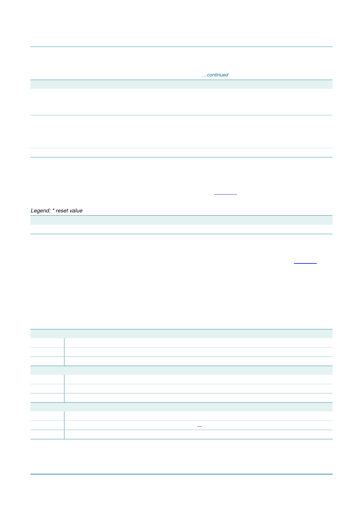
Table 9. STATUS - Status register (address 06h) bit description …continued
Bit
Symbol Description
5
66MC
66 MHz Capable: This read-only bit indicates whether this device is capable of running at 66 MHz.
0 — 33 MHz
1 — 66 MHz
4
CL
Capabilities List: This read-only bit indicates whether this device implements the pointer for a new
capabilities linked list at offset 34h.
0 — No new capabilities linked list is available.
1 — The value read at offset 34h is a pointer in configuration space to a linked list of new capabilities.
3 to 0 reserved -
8.2.1.5 Revision ID register
This 1-byte read-only register indicates a device-specific revision identifier. The value is
chosen by the vendor. This field is a vendor-defined extension of the device ID. The
Revision ID register bit description is given in Table 10.
Table 10. REVID - Revision ID register (address 08h) bit description
Legend: * reset value
Bit Symbol Access Value Description
7 to 0 REVID[7:0] R
11h* Revision ID: This byte specifies the design revision number of functions.
8.2.1.6 Class Code register
Class Code is a 24-bit read-only register used to identify the generic function of the
device, and in some cases, a specific register-level programming interface. Table 11
shows the bit allocation of the register.
The Class Code register is divided into three byte-size fields. The upper byte is a base
class code that broadly classifies the type of function the device performs. The middle
byte is a sub-class code that identifies more specifically the function of the device. The
lower byte identifies a specific register-level programming interface, if any, so that
device-independent software can interact with the device.
Table 11. CC - Class Code register (address 09h) bit allocation
Bit
23
22
21
20
19
18
17
16
Symbol
BCC[7:0]
Reset
0Ch
Access
R
R
R
R
R
R
R
R
Bit
15
14
13
12
11
10
9
8
Symbol
SCC[7:0]
Reset
03h
Access
R
R
R
R
R
R
R
R
Bit
7
6
5
4
3
2
1
0
Symbol
RLPI[7:0]
Reset
X[1]
Access
R
R
R
R
R
R
R
R
[1] X is 10h for OHCI1 and OHCI2; X is 20h for EHCI.
ISP1562_3
Product data sheet
Rev. 03 — 14 November 2008
© NXP B.V. 2008. All rights reserved.
18 of 93
Share Link: 