ISL6271AEVAL1 データシートの表示(PDF) - Intersil
部品番号
コンポーネント説明
一致するリスト
ISL6271AEVAL1 Datasheet PDF : 14 Pages
| |||
Setup Instructions for the ISL6271A Evaluation Kit
Dynamic Voltage Management(DVM)
via I2C
The following steps will guide the evaluator through
the set-up required to control both the voltage level
and slew rate of Vcore dynamically from a PC over a
USB-to-I2C interface. The user will be able to easily
set the core voltage at any one of 16 discrete levels
between 0.85V and 1.3V, and the slew rate to one of
4 discrete levels from .1mV/uS to 5mV/uS (see data
sheet) simply by selecting the desired level(s) and
commanding a ‘writeI2C’ to the device.
Load Driver Software
The first step is to connect the USB-I2C interface
module to the PC USB port with the supplied cable
(Figure 10) .
Next install the driver software for the I2C interface,
provided on the same evaluation kit CD as this
document (see Appendix B), and by following the
installation instructions provided in Appendix B.
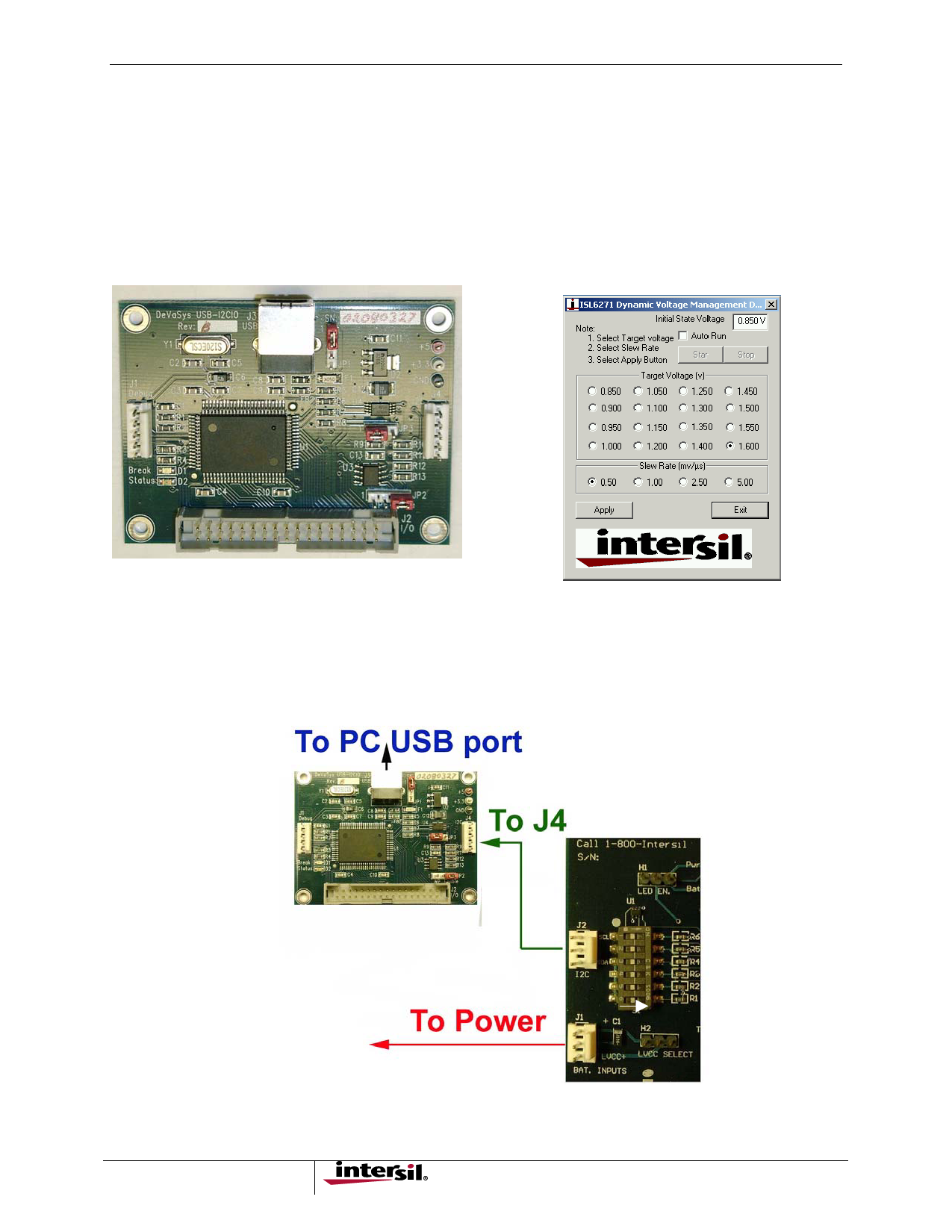
The screen below will appear after the application
software is installed and the testing application is
executed.
FIGURE 10. THE USB I2C INTERFACE MODULE
FIGURE 11. ISL6271A TESTING APPLICATION
WINDOW
Hardware Module(s) Interconnect
Once the SW is loaded and the DVM-choice screen is displayed (Figure 11), the two boards should be connected
together ( Figure 12). Before connecting the cable between the eval board and the USB-I2C module (Figure 2),
apply input power (3.7V) to the eval board and then connect the interconnecting cable to J2 on the eval board.
Switch S1 position 6 should be switched to the ‘right’ for I2C testing.
FIGURE 12. CONNECT THE INTERCONNECTING CABLE TO J2 ON THE EVALUATION BOARD
7
Share Link: 