ISL6271AEVAL1 データシートの表示(PDF) - Intersil
部品番号
コンポーネント説明
一致するリスト
ISL6271AEVAL1 Datasheet PDF : 14 Pages
| |||
Setup Instructions for the ISL6271A Evaluation Kit
Initial Set-Up
Position the ISL6271A eval board so that the Intersil logo is in the upper right corner, relative to testers perspective.
All switch positions on S1 should be to the ‘left’ to Enable the device for static VID input.
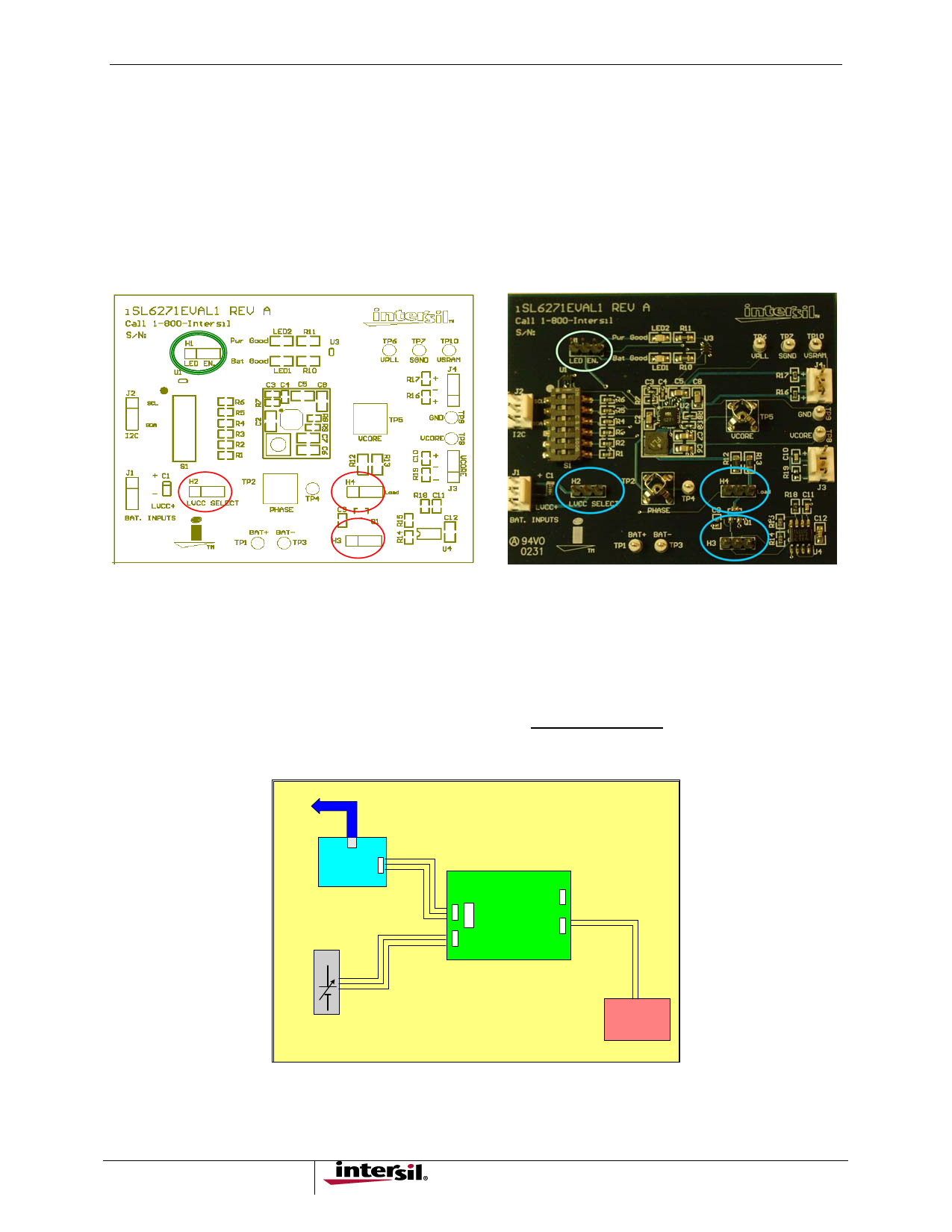
Place shunts as follows, (see Figure 1):
H1 to ‘enable’
H2 no shunt (if external LVCC being supplied, left two pins should never be shorted)
H3 no shunt
H4 no shunt
FIGURE 1. SHUNT PLACEMENT ON H1 TO ENABLE, AND NO SHUNT ON H2, H3 AND H4
Adjust the External Power Supplies to 3.7V and 2.5V respectively, and turn off.
NOTE: (Under NO circumstances should the voltage on either supply be allowed to exceed 6.0V)
Adjust the external electronic load for a constant current of 200mA (Do not interconnect).
Connect J1 on the eval board to the dual power supply, with the (LVCC+) pin to 2.5V (supply to the 2 LDO’s), the (+)
pin to 3.7V (supply to the swiching regulator), and the (-) pin to the supply common (gnd), Figure 2.
To PC USB
USB-I2C
I2C
ISL6271EVAL1
J4
(For DVM Testing Only)
J2
Power
J1
S1
J3
LOAD
FIGURE 2. CONNECT J1 TO THE DUAL POWER SUPPLY
2
Share Link: 