ISL6271AEVAL1 データシートの表示(PDF) - Intersil
部品番号
コンポーネント説明
一致するリスト
ISL6271AEVAL1 Datasheet PDF : 14 Pages
| |||
Setup Instructions for the ISL6271A Evaluation Kit
Connect J3 on evaluation board to the electronic load, (Figure 7), observing proper polarities.
T
O
L
O
A
D
FIGURE 7. CONNECT THE J3 ON THE EVALUATION BOARD TO THE ELECTRONIC LOAD
NOTE: (Fixed resistive loads of 1Kohm each are connected across the VPLL and VSRAM outputs onboard. If variable loading is
desired, such a load can be connected via J4)
Reapply power and observe DVM#2 indicating 1.3V and that the load is sinking 200mA.
Basic functionality is confirmed and thorough testing/characterization can begin.
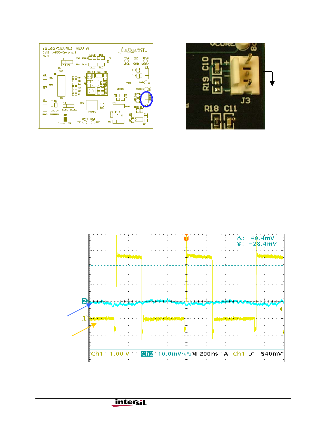
TP5 and TP2 will accommodate low-noise Tek scope probe tips for monitoring the AC characteristics of Vcore and
Phase, respectively.
The phase node is a good signal point from which to trigger and observe cycle-by-cycle switching behavior of the
Vcore regulator. Connect the trigger channel to the TP2 probe point to trigger on the phase signal. See Figure 8 for a
typical scope shot of the Vcore voltage(AC) when triggered from the phase node.
Vcore
Phase
FIGURE 8. VCORE AND PHASE
5
Share Link: 