ISL6271AEVAL1 データシートの表示(PDF) - Intersil
部品番号
コンポーネント説明
一致するリスト
ISL6271AEVAL1 Datasheet PDF : 14 Pages
| |||
Setup Instructions for the ISL6271A Evaluation Kit
Transient Load Testing w/onboard Transient Generator
The onboard transient generator function permits dynamically changing the load current on Vcore and is enabled by
placing a shunt across H4 pins 2-3 (while H1 is enabled), see Figure 1. This periodically connects and disconnects a
5 ohm load across the Vcore output at about a 1 second interval, corresponding to about a 250mA pulse load on the
output at 1.3V. H4 pin 2 can then be used to trigger the scope and observe the effect on Vcore each time this load
switches in either the positive or negative direction, thus observing the transient response of the Vcore regulator. This
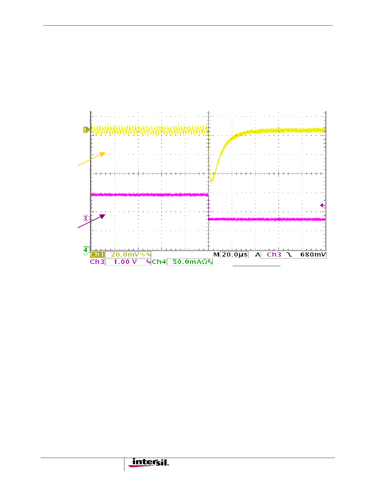
is illustrated below in Figure 9 with a 10mA external load bias applied. (Note: The output load can be biased to some
DC level by an external load connected through J3) . A programmable external load may provide more versatility for
transient load testing, but this on-board capability gives an excellent read on the regulators response characteristic.
Vcore
H4-Pin2
FIGURE 9. VCORE TRANSIENT RESPONSE (10MA – 250MA)
Efficiency Measurement Considerations
Since the ISL6271A is a multi-regulator PMIC, it is important to segregate the regulators as much as possible when
attempting accurate efficiency measurements on the core regulator. The power input to the LDOs (LVCC) can be tied
to the main PVCC input by a strap on H2, but should be separated from the core regulator input voltage (PVCC)
during efficiency measurements. All other extraneous draw from PVCC should be removed, such as the LED power
and the transient generator circuitry. Removing the shunt from H1 effectively removes power from both the LED and
transient-generator circuits, and prepares the circuit for core regulator efficiency measurements.
Another drain to take into consideration, if efficiency testing is being done under static VID control, is the 100K pull-up
resistors for the switches in S1, which will drain 30-40uA each from PVCC when in the ‘right’ position. If testing is
being done at an output voltage of less than 1.3V (all ‘left’), then the number of switches in the ‘right’ position should
be factored into the efficiency calculation. This should be a relatively insignificant factor at higher output current
levels, but it is a factor to be cognizant of.
6
Share Link: 