ISL6271AEVAL1 データシートの表示(PDF) - Intersil
部品番号
コンポーネント説明
一致するリスト
ISL6271AEVAL1 Datasheet PDF : 14 Pages
| |||
Setup Instructions for the ISL6271A Evaluation Kit
Connect the test leads of DVM#1 between TP1(+) and TP3(-) and set to measure VDC.
Connect the test leads of DVM#2 between TP8(+) and TP9(-) and set to measure VDC.
Connect the test leads of DVM#3 between TP6(+) and TP7(-) and set to measure VDC.
DVM #3
DVM #2
DVM #1
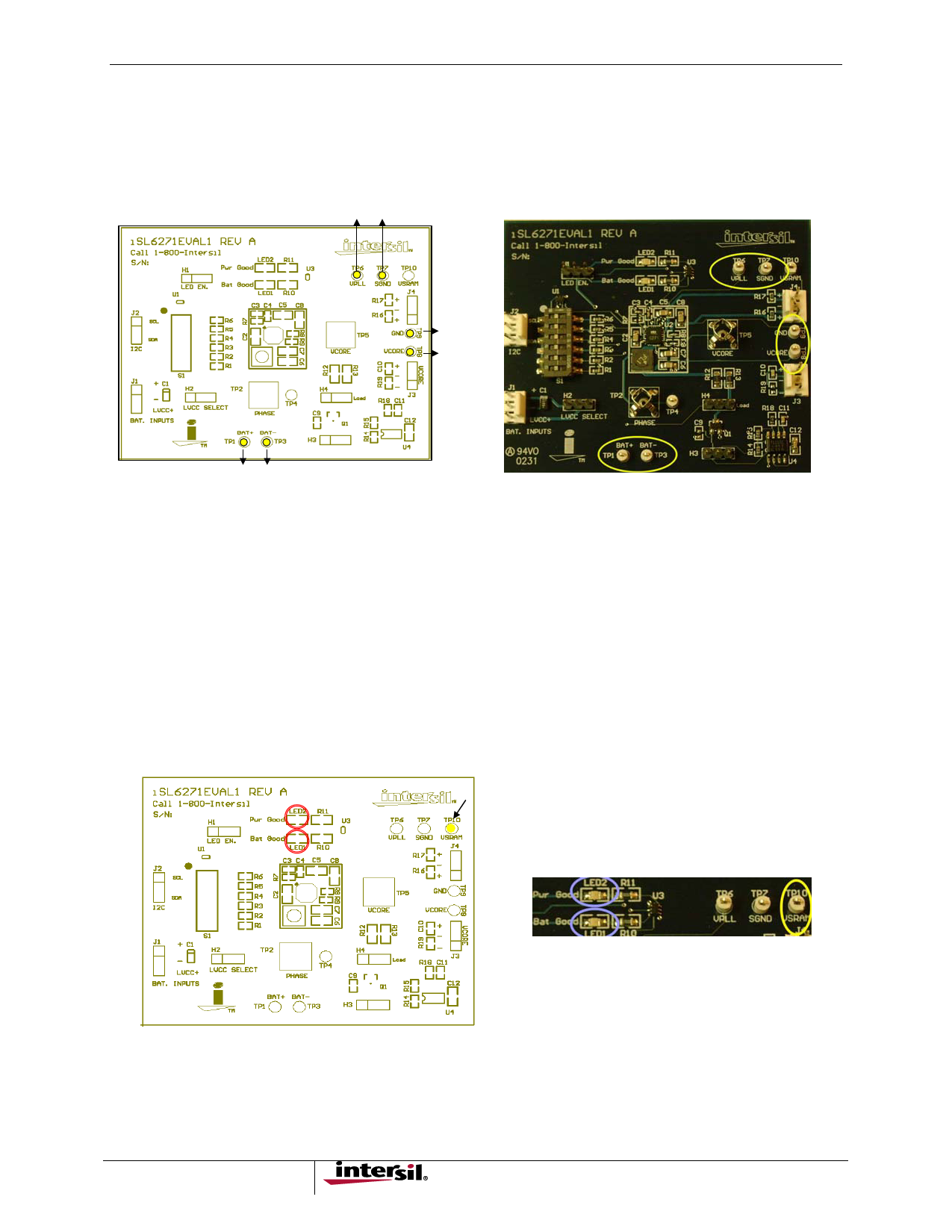
FIGURE 3. CONNECT THE TEST LEADS BETWEEN TP1, TP3, TP8, TP9, TP6, TP7
Initial Power-Up
With all the switches of S1 on the eval board at “off” positions and the external supplies adjusted to 3.7V and 2.5V,
turn both power supplies ‘on’.
Observe that both LEDs (LED1, LED2) are illuminated, see Figure 4.
Confirm DVM#2 indicates 1.6V (+-25mV) for VCore
Confirm DVM#1 indicates 3.7V (+-50mV) this voltage will vary with the load current
Confirm DVM#3 indicates 1.3V (+-25mV) for VPLL
Move DVM#3 (+) lead to TP10 and confirm 1.1V(+-25mV) for VSRAM
FIGURE 4. OBSERVE LED1, LED2 AND CONFIRM VOLTAGES
3
Share Link: 