PDI1394L21 データシートの表示(PDF) - Philips Electronics
部品番号
コンポーネント説明
一致するリスト
PDI1394L21 Datasheet PDF : 52 Pages
| |||
Philips Semiconductors
1394 full duplex AV link layer controller
Preliminary specification
PDI1394L21
13.2.12 Isochronous Receiver Interrupt Enable (IRXINTE) – Base Address: 0x050
Interrupt enable bits for AV Receiver.
31 30 29 28 27 26 25 24 23 22 21 20 19 18 17 16 15 14 13 12 11 10 9 8 7 6 5 4 3 2 1 0
SV00888
Reset Value 0x00000000
Bit 10..0 are interrupt enable bits for the Isochronous Receiver Interrupt Acknowledge (IRXINTACK).
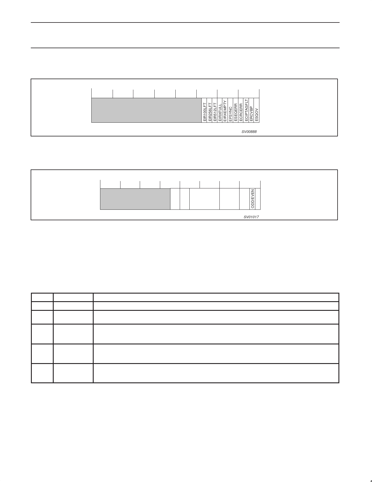
13.2.13 Isochronous Receiver Control Register (IRXCTL) – Base Address: 0x054
31 30 29 28 27 26 25 24 23 22 21 20 19 18 17 16 15 14 13 12 11 10 9 8 7 6 5 4 3 2 1 0
SPD TAG CHANNEL
ERR
SV01017
Reset Value 0x00000000
Bit 17..16:
R
SPD: Speed of last received isochronous packet (S100 .. S400).
00 = 100 Mbps
01 = 200 Mbps
10 = 400 Mbps
11 = Reserved
Bit 15..14:
R/W TAG: Isochronous tag value (must match) for AV format, ‘01’ for IEC 61883 International Standard data.
Bit 13..8:
R/W CHAN: Channel number to receive isochronous data.
Bit 7..4:
R
ERR: Error code for last received isochronous AV packet.
Table 9. Error Codes
Code
Name
0000 reserved
0001 ack_complete
0010
through reserved
1100
Meaning
The node has successfully accepted the packet. If the packet was a request subaction, the destination node has
successfully completed the transaction and no response subaction shall follow.
1101
ack_data_error
The node could not accept the block packet because the data field failed the CRC check, or because the length
of the data block payload did not match the length contained in the dataLength field. this code shall not be
returned for any packet that does not have a data block payload.
1110
and
1111
reserved
Bit 3..0:
R
SYNC: Last received SY code in isochronous bus packet header. Bit 1 is odd/even encryption bit key. State of this bit
will be outputted at active (receiving) AVPORT on the AVxENKEY pin while the accompanying application packet is
being outputted. Also see Section 13.2.6 for a description of the operation of this bit..
1999 Aug 06
39
Share Link: 