PDI1394L21 データシートの表示(PDF) - Philips Electronics
部品番号
コンポーネント説明
一致するリスト
PDI1394L21 Datasheet PDF : 52 Pages
| |||
Philips Semiconductors
1394 full duplex AV link layer controller
Preliminary specification
PDI1394L21
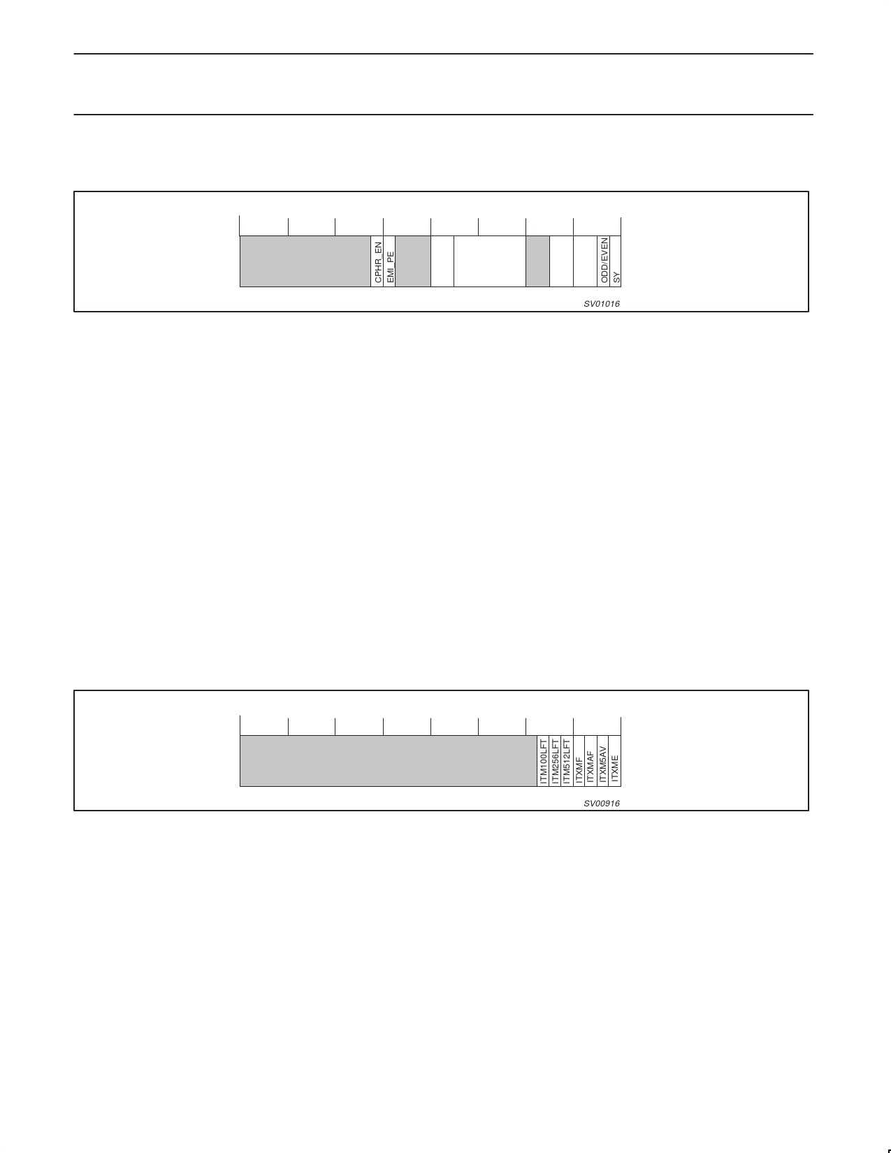
13.2.6 Isochronous Transmitter Control Register (ITXCTL) – Base Address: 0x34
31 30 29 28 27 26 25 24 23 22 21 20 19 18 17 16 15 14 13 12 11 10 9 8 7 6 5 4 3 2 1 0
TAG CHANNEL
SPD EMI
SV01016
Reset Value 0x00000000
Bit 15..14:
R/W Tag: Tag code to insert in isochronous bus packet header. Should be ‘01’ for IEC 61883 International Standard data.
Bit 13..8:
R/W Channel: Isochronous channel number.
Bit 5..4:
R/W Speed: Cable transmission speed (S100, S200, S400).
00 = 100Mbs
01 = 200Mbs
10 = 400Mbs
11 = reserved
Bit 3..0
R
Sync: Code to insert in SY field of isochronous bus packet header. Bit 1 is odd/even bit used for encryption key
(0 = even, 1 = odd). Bit value determined by state of transmit port AVxENKEY pin. Some data encryption schemes
require that an ODD/EVEN bit accompany each application packet sent for the purpose of changing “keys” after
short intervals of time (makes breaking an encryption code more difficult). The PDI1394L21 uses the sync field
ODD/EVEN bit for this purpose. Data is inputted to the transmitting AV port accompanied by the state of the
ODD/EVEN bit presented to the AVx ENKEY pin. The pin state at the rising edge of the AVCLK as the first byte of
the packet determines the ODD/EVEN “key” state for that packet. The ODD/EVEN key state may change as often as
required, provided that 2 key changes do not appear in the transmit FIFO simultaneously. If this rule is observed, the
proper “key” state will accompany the packet on to the 1394 bus and through the receiving node’s receive FIFO. As
the packet is being outputted at the receive node’s PDI1394L21, the accompanying ODD/EVEN key state will be
output. The key state remains for all bytes of the packet. Typical change rates for the ODD/EVEN key are between
1 change per second and a change every 30 seconds.
13.2.7 Isochronous Transmitter Memory Status (ITXMEM) – Base Address: 0x038
The AV Transmitter Memory Status register reports on the condition of the internal memory buffer used to store incoming AV data streams
before transmission over the 1394 bus.
3130 29 28 27 26 25 24 23 22 21 20 19 18 17 16 15 14 13 12 11 10 9 8 7 6 5 4 3 2 1 0
SV00916
Reset Value 0x00000003
Bit 6:
R
ITM100LFT: Memory has 100 quadlets of space remaining before becoming full.
Bit 5:
R
ITM256LFT: Memory has 256 quadlets of space remaining before becoming full.
Bit 4:
Bit 3:
R
IITM512LFT: Memory is 1/2 full.
R
ITXMF: memory is completely full, no storage available.
Bit 2:
R
ITXMAF: almost full, exactly one quadlet of storage available.
Bit 1:
R
ITXM5AV: at least 5 more quadlets of storage available.
Bit 0:
R
ITXME: memory bank is empty (zero quadlets stored).
1999 Aug 06
36
Share Link: 