MC100EL34DG(2016) データシートの表示(PDF) - ON Semiconductor
部品番号
コンポーネント説明
一致するリスト
MC100EL34DG Datasheet PDF : 9 Pages
| |||
MC10EL34, MC100EL34
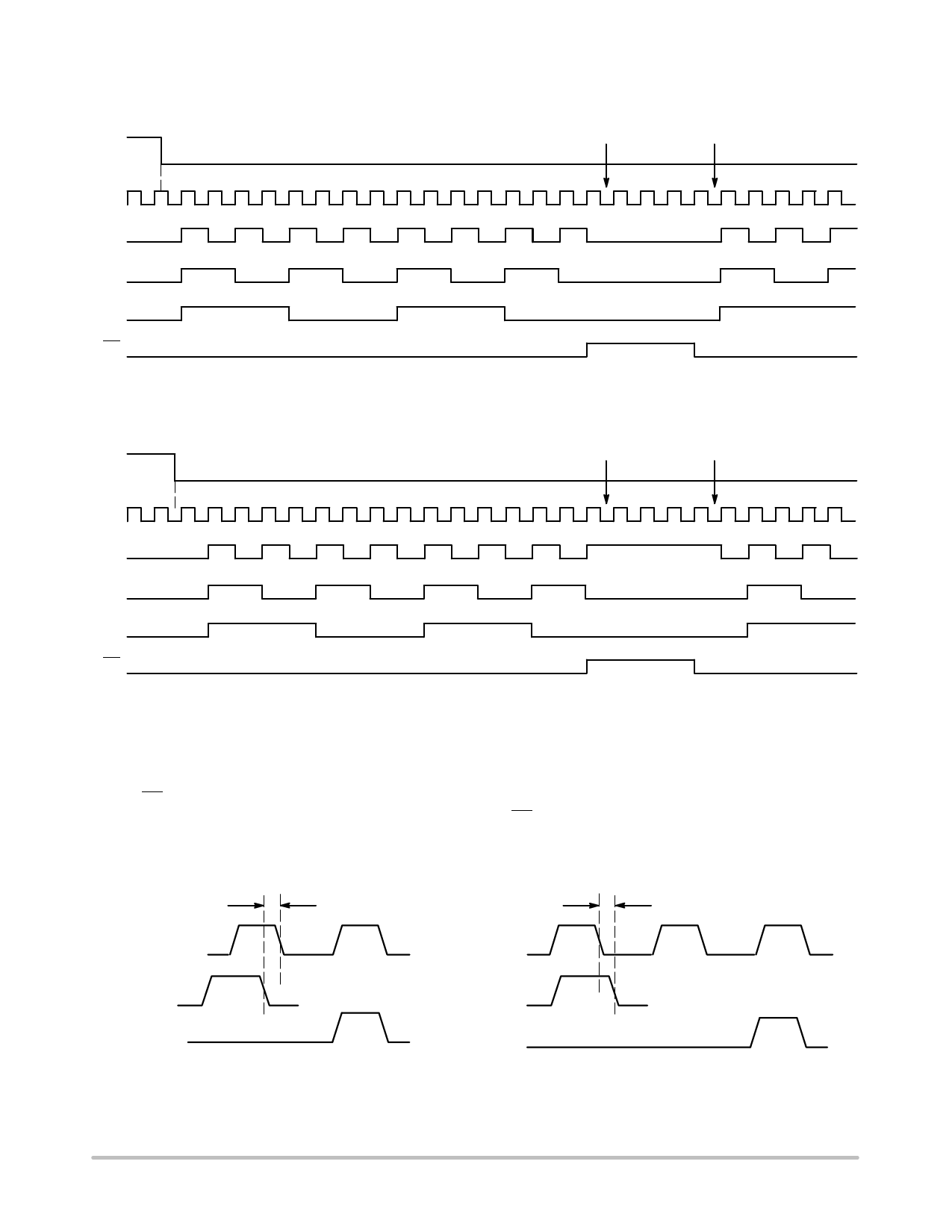
There are two distinct functional relationships between the Master Reset and Clock:
Internal Clock
Disabled
MR
Internal Clock
Enabled
CLK
Q0
Q1
Q2
EN
CASE 1: If the MR is De-asserted (H−L), While the Clock is Still High, the
Outputs will Follow the First Ensuing Clock Rising Edge.
Internal Clock
Disabled
Internal Clock
Enabled
MR
CLK
Q0
Q1
Q2
EN
CASE 2: If the MR is De−asserted (H−L), After the Clock has Transitioned Low, the
Outputs will Follow the Second Ensuing Clock Rising Edge.
Figure 2. Timing Diagrams
The EN signal will “freeze” the internal divider flip−flops on the first falling edge of CLK after its assertion. The internal
divider flip−flops will maintain their state during the freeze. The EN is deasserted (LOW), and after the next falling edge
of CLK, then the internal divider flip−flops will “unfreeze” and continue to their next state count with proper phase rela-
tionships.
TRR
CLOCK
TRR
CLOCK
MR
OUTPUT
CASE 1
MR
OUTPUT
Figure 3. Reset Recovery Time
CASE 2
www.onsemi.com
6
Share Link: 