54HCT163 データシートの表示(PDF) - Unspecified
部品番号
コンポーネント説明
一致するリスト
54HCT163 Datasheet PDF : 9 Pages
| |||
High Speed CMOS TTL Input – 74HCT163
Function Description
Rev 1.0
06/06/19
INPUTS
Clock (CP - Pad 2)
The internal flip–flops toggle and the output count
advances with the rising edge of the Clock input. In
addition, control functions such as resetting and loading
occur with the rising edge of the Clock Input.
Preset Data Inputs (P0, P1, P2, P3 - Pads 3, 4, 5, 6)
These are the data inputs for programmable counting.
Data on these pins may be synchronously loaded into the
internal flip–flops and appear at the counter outputs. P0
(Pad 3) is the least–significant bit and P3 (Pad 6) is the
most–significant bit.
OUTPUTS
Q0, Q1, Q2, Q3 (Pads 14, 13, 12, 11)
These are the counter outputs. Q0 (Pad 14) is the least–
significant bit and Q3 (Pad 11) is the most–significant bit.
Ripple-Carry Out (TC - Pad 15)
When the counter is in it’s maximum state 1111, this
output goes high, providing an external look–ahead carry
pulse that may be used to enable successive cascaded
counters. Ripple Carry Out remains high only during the
maximum count state. Logic equation for this output is:
Ripple Carry Out (TC) = T Enable (TE) • Q0 • Q1 • Q2 • Q3
CONTROL FUNCTIONS
Reset (MR – Pad 1)
A low level on Reset resets the internal flip– flops & sets
the outputs (Q0 through Q3) to a a low level. Reset is
synchronous with the rising edge of the Clock input.
Synchronous Parallel Enable (SPE - Pad 9)
With the rising edge of the Clock, a low level on SPE
loads the data from the Preset Data input pads (P0, P1,
P2, P3) into the internal flip–flops and onto the output
pins, Q0 through Q3. The count function is
disabled as long as Load is low.
Count Enable/Disable (PE and TE - Pads 7, 10)
The device has two count–enable control pins: P Enable
P (PE) and T Enable (TE). The device counts when these
two pads and the Data load pad are high. The logic
equation is:
Count Enable = P Enable • T Enable • Data Load
The count is either enabled or disabled by the control
inputs according to Figure 1. In general, P Enable (PE) is
a count–enable control: T Enable (TE) is both a count–
enable and a Ripple–Carry Output control.
Count Enable / Disable truth table
CONTROL INPUTS
SPE PE TE
RESULT AT OUTPUTS
Q0-Q3
TC
H
HH
COUNT
HIGH WHEN Q0–Q3 ARE MAX
L
H H NO COUNT HIGH WHEN Q0–Q3 ARE MAX
X
L
H NO COUNT HIGH WHEN Q0–Q3 ARE MAX
X
X
L NO COUNT
L
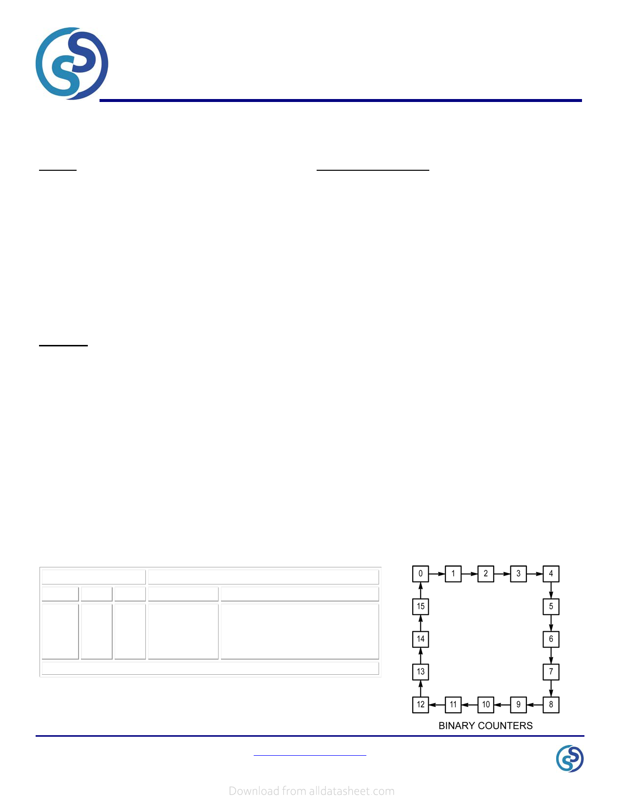
Q0 through Q3 are maximum when Q3 Q2 Q1 Q0 = 1111.
Output State Diagram
Page 3 of 9
www.siliconsupplies.com
Share Link: 