IDT82V2048(2010) データシートの表示(PDF) - Integrated Device Technology
部品番号
コンポーネント説明
一致するリスト
IDT82V2048 Datasheet PDF : 62 Pages
| |||
IDT82V2048 OCTAL T1/E1 SHORT HAUL LINE INTERFACE UNIT
INDUSTRIAL TEMPERATURE RANGES
Table-1 Pin Description (Continued)
Name
Pin No.
Type
TQFP144 PBGA160
Description
SDO: Serial Data Output
In serial host mode, the data is output on this pin. In serial write operation, SDO is in high impedance for
the first 8 SCLK clock cycles and driven low for the remaining 8 SCLK clock cycles. In serial read opera-
tion, SDO is in high-Z only when SDI is in address/command byte. Data on pin SDO is clocked out of the
device on the falling edges of SCLK if pin CLKE is high, or on the rising edges of SCLK if pin CLKE is low.
SDO/RDY/ACK
O
83
K14 RDY: Ready Output
In parallel Intel host mode, the high level of this pin reports to the host that bus cycle can be completed,
while low reports the host must insert wait states.
O
INT
Open
82
Drain
LP7/D7/AD7
28
LP6/D6/AD6
27
LP5/D5/AD5
I/O
26
LP4/D4/AD4
25
LP3/D3/AD3
24
LP2/D2/AD2 High-Z
23
LP1/D1/AD1
22
LP0/D0/AD0
21
ACK: Acknowledge Output (Active Low)
In parallel Motorola host mode, the low level of this pin indicates that valid information on the data bus is
ready for a read operation or acknowledges the acceptance of the written data during a write operation.
INT: Interrupt (Active Low)
K13 This is an open drain, active low interrupt output. Four sources may cause the interrupt . Refer to 2.19
Interrupt Handling for details.
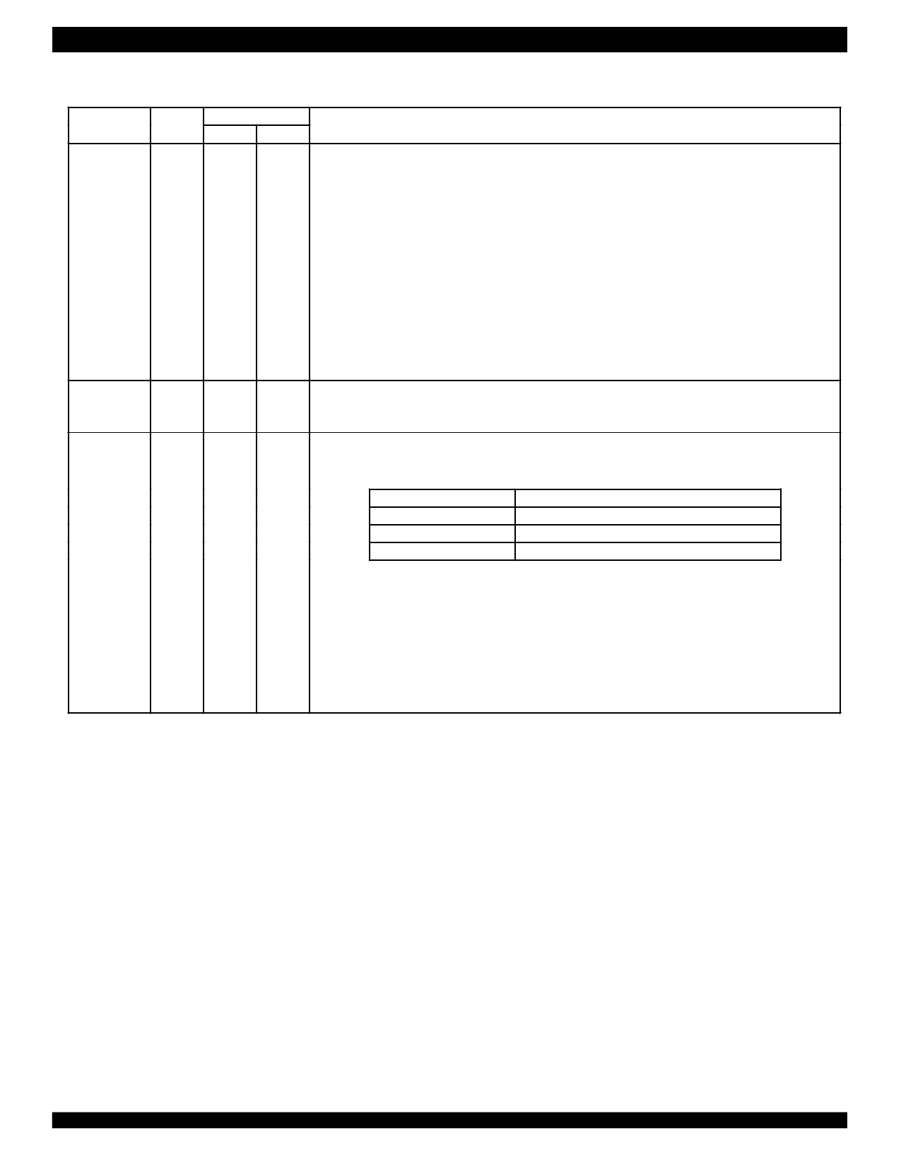
LPn: Loopback Select 7~0
In hardware control mode, pin LPn configures the corresponding channel in different loopback mode, as
follows:
LPn
Loopback Configuration
K1
Low
Remote Loopback
J1
VDDIO/2
No loopback
J2
High
Analog Loopback
J3 Refer to 2.17 Loopback Mode for details.
J4
H2 Dn: Data Bus 7~0
H3 In non-multiplexed host mode, these pins are the bi-directional data bus.
G2
ADn: Address/Data Bus 7~0
In multiplexed host mode, these pins are the multiplexed bi-directional address/data bus.
In serial host mode, these pins should be grounded.
9
Share Link: 