IDT82V2048(2010) データシートの表示(PDF) - Integrated Device Technology
部品番号
コンポーネント説明
一致するリスト
IDT82V2048 Datasheet PDF : 62 Pages
| |||
IDT82V2048 OCTAL T1/E1 SHORT HAUL LINE INTERFACE UNIT
INDUSTRIAL TEMPERATURE RANGES
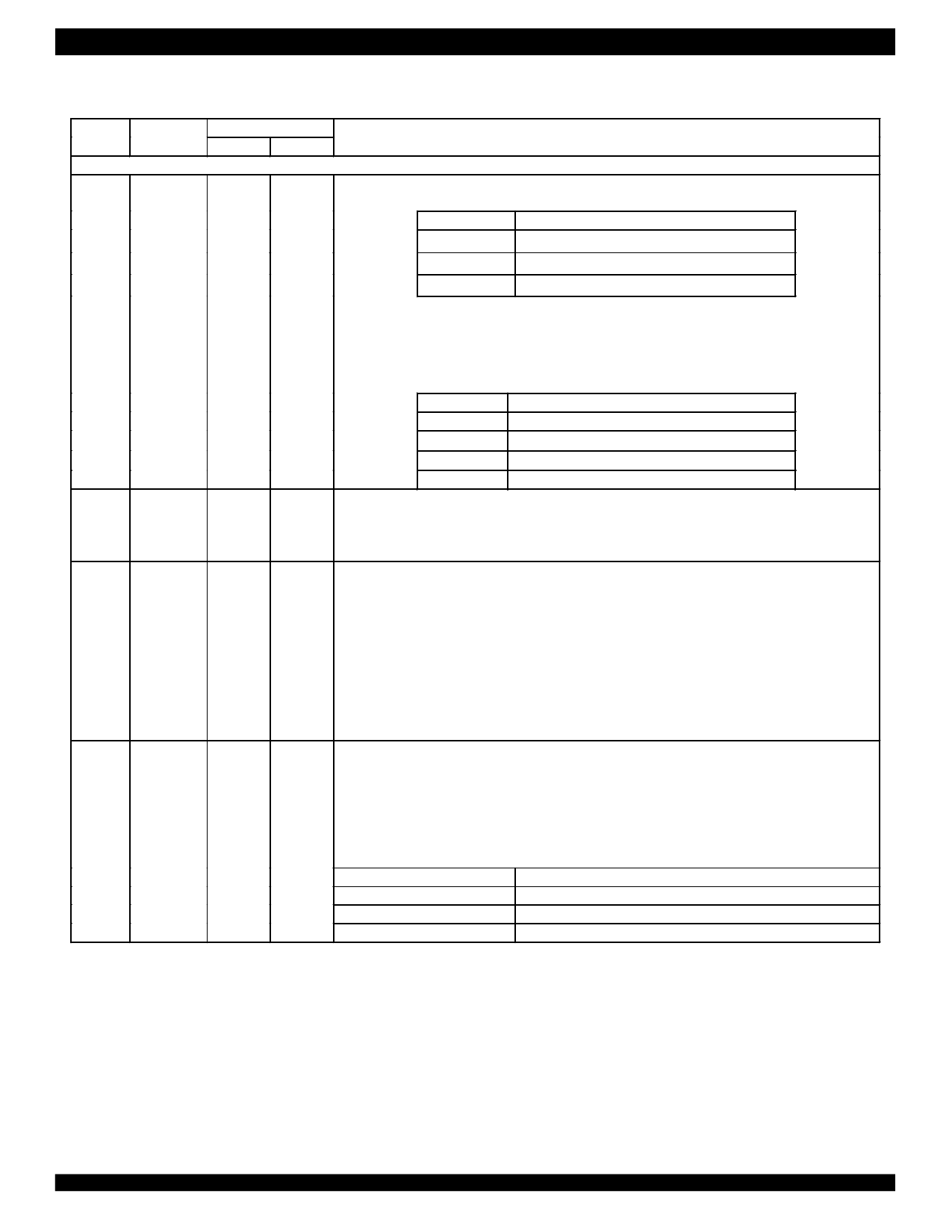
Table-1 Pin Description (Continued)
Name
MODE2
Pin No.
Type
TQFP144 PBGA160
Description
Hardware/Host Control Interface
MODE2: Control Mode Select 2
The signal on this pin determines which control mode is selected to control the device:
MODE2
Low
VDDIO/2
High
Control Interface
Hardware Mode
Serial Host Interface
Parallel Host Interface
I
(Pulled to
11
VDDIO/2)
Hardware control pins include MODE[2:0], TS[2:0], LP[7:0], CODE, CLKE, JAS and OE.
E2
Serial host Interface pins include CS, SCLK, SDI, SDO and INT.
Parallel host Interface pins include CS, A[4:0], D[7:0], WR/DS, RD/R/W, ALE/AS, INT and RDY/ACK. The
device supports multiple parallel host interface as follows (refer to MODE1 and MODE0 pin descriptions
below for details):
MODE[2:0]
100
101
110
111
Host Interface
Non-multiplexed Motorola Mode Interface
Non-multiplexed Intel Mode Interface
Multiplexed Motorola Mode Interface
Multiplexed Intel Mode Interface
MODE1: Control Mode Select 1
MODE1
I
43
K2
In parallel host mode, the parallel interface operates with separate address bus and data bus when this pin
is low, and operates with multiplexed address and data bus when this pin is high.
In serial host mode or hardware mode, this pin should be grounded.
MODE0: Control Mode Select 0
In parallel host mode, the parallel host interface is configured for Motorola compatible hosts when this pin
is low, or for Intel compatible hosts when this pin is high.
MODE0/CODE
I
88
H12
CODE: Line Code Rule Select
In hardware control mode, the B8ZS (for T1 mode)/HDB3 (for E1 mode) encoder/decoder is enabled when
this pin is low, and AMI encoder/decoder is enabled when this pin is high. The selections affect all the
channels.
I
CS/JAS
(Pulled to
87
VDDIO/2)
In serial host mode, this pin should be grounded.
CS: Chip Select (Active Low)
In host mode, this pin is asserted low by the host to enable host interface. A high to low transition must
occur on this pin for each read/write operation and the level must not return to high until the operation is
over.
JAS: Jitter Attenuator Select
J11 In hardware control mode, this pin globally determines the Jitter Attenuator position:
JAS
Low
VDDIO/2
High
Jitter Attenuator (JA) Configuration
JA in transmit path
JA not used
JA in receive path
7
Share Link: 