CDB6403 データシートの表示(PDF) - Cirrus Logic
部品番号
コンポーネント説明
一致するリスト
CDB6403 Datasheet PDF : 54 Pages
| |||
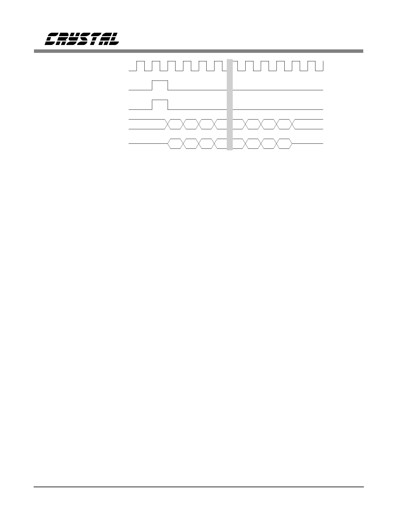
CS6403
SCLK (in)
SSYNC (in)
SYNCOUT (out)
SDI (in)
b15 b14 b13 b12 b3 b2 b1 b0
SDO (out)
b15 b14 b13 b12 b3 b2 b1 b0
Figure 8. Serial Port Timing for Mode 2 (16-bit) - SLAVE
Mode 2 (8-bit) Slave
Mode 2 (8-bit) provides a slaved SSI which may
be needed for 8-bit companded audio interfacing,
as is the case with many ISDN transceivers.
Mode 2 (8-bit) timing is similar to Mode 2 (16-
bit) timing, but the serial data is 8-bit
companded, with the type of companding deter-
mined by the state of the UALAW pin. All 8
bits are used for audio, so no steering bit is nec-
essary, and consequently, no control information
can be transferred in this mode.
If STR, the Steering Bit (b15), is zero, then the
data transferred on the Serial Interface is audio
data. Note that since a transfer typically consists
of 16 bits, this allows 15-bit precision for input
audio data. Output audio data remains in 16-bit
precision.
Companded audio data is treated differently than
16-bit data. Input companded audio data has
eight zeroes followed by the 8-bit companded
data. Output companded audio data is formatted
such that 8-bit data is followed by eight zeroes.
Mode 2 (8-bit) is selected by setting CONFIG
low, as opposed to high in Mode 2 (16-bit). See
Table 2 for more details. SCLK frequency is de-
termined by the SCLK_RATE1 and
SCLK_RATE0 pins as given by Table 1. As in
Mode 2 (16-bit), the CS6403 will phase-lock to
the SCLK provided to it and derive its own tim-
ing from it.
Mode 2 (16-bit) Slave
Setting CONFIG high selects Mode 2 (16-bit).
When a DSP is connected to a CS6403 in
Mode 2 (16-bit), the DSP can reconfigure the
CS6403 by writing to the CS6403’s control reg-
isters via the SSI. To multiplex both data and
control on one serial interface, a steering bit is
used. The first bit sent (MSB) by the DSP deter-
mines whether a word is control or data, as
shown in Table 3.
If STR is one, the word transferred on the Serial
Interface is control information. If the RNW bit
is a zero, the word written by the external DSP
is stored by the CS6403 in the indicated destina-
tion register, and simultaneously, the state of the
destination register before the write is read back
into the DSP. If RNW is one, the data written
by the external DSP is ignored. The state of the
destination register is read back to the DSP.
Note that only one control word or one data
word may be transferred in a sample time, mean-
ing that no audio data is transferred in sample
times where control information is transferred. In
such sample times, the CS6403 will reuse (dou-
ble-sample) the audio data from the previous
sample time. As a result, to minimize distortion
of the audio signal, control transactions should
be made infrequently.
16
DS192PP6
Share Link: 