CDB6403 データシートの表示(PDF) - Cirrus Logic
部品番号
コンポーネント説明
一致するリスト
CDB6403 Datasheet PDF : 54 Pages
| |||
CS6403
audio and control data while SLP is asserted, by-
passing the CPU and AFP. Note, however, that
since the CPU is powered down, no scaling is
performed on the ADC input, no echo is can-
celled, and audio data is not companded.
Using the CS6403
Interfacing as a Master to an external codec
(Mode 1)
In applications like speakerphones, it is possible
to connect the CS6403 directly to an external
network codec. An example circuit is shown in
Figure 5.
In this application, SYNCOUT and SCLK are
sourced by the CS6403 (i.e., SMASTER=1), and
CLKIN is generated by connecting a crystal be-
tween CLKOUT and CLKIN. The timing for
these signals is illustrated in Figure 6.
Audio-data samples in Mode 1 are 8 bits and are
µ−law or A-law companded depending on the
state of the UALAW pin (PIN 13Q, 19L). No
control information can be transferred in Mode
1, so there is no control/data steering bit. Also
note that since control information cannot be
transferred, the default settings of the control
registers established after Reset are used.
In Mode 1, 80 echo-canceller taps (out of the
available 512) are permanently allocated to net-
work-echo cancellation (see Figure 3).
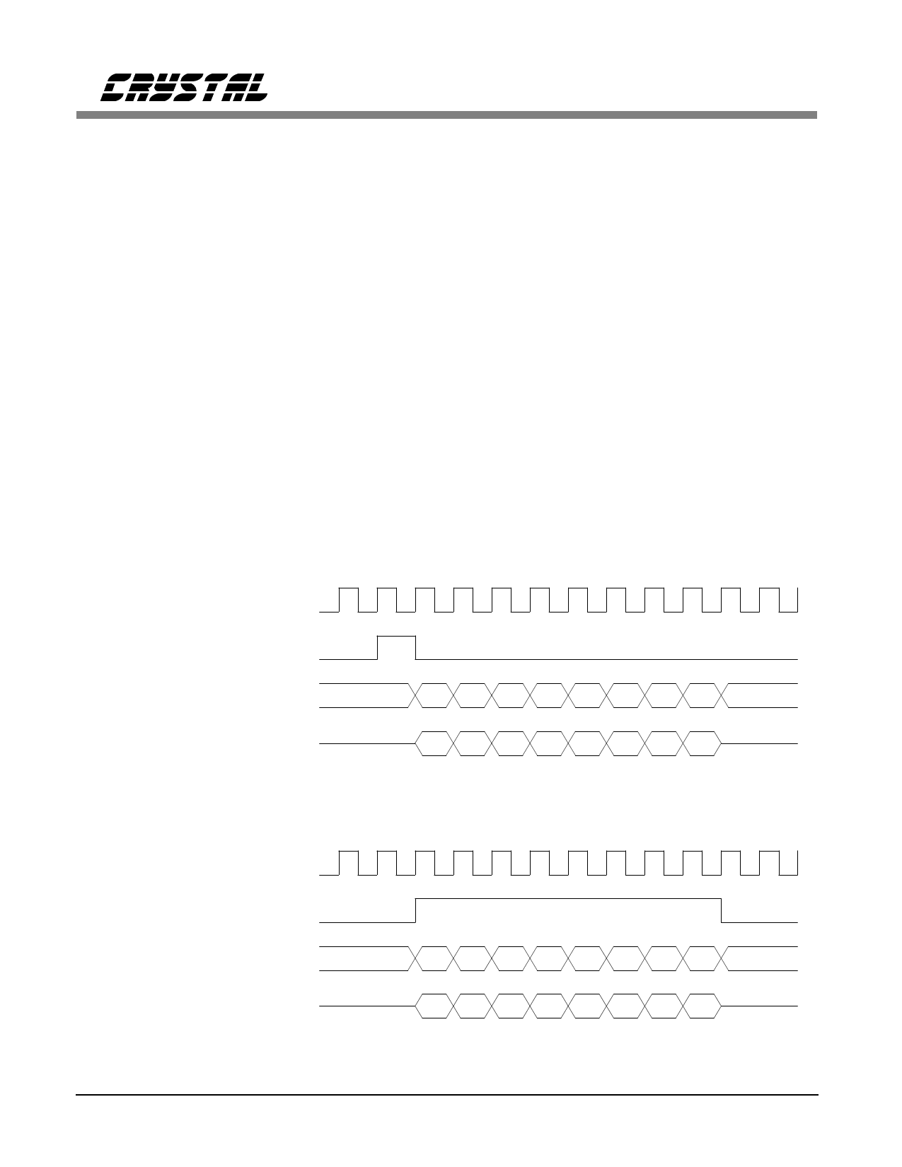
Mode 1.1 (Short-Frame Mode)
SFRAME=0; SSYNC = 0
SCLK (out)
SYNCOUT (out: 8kHz)
SDI (in)
SDO (out)
b7 b6 b5 b4 b3 b2 b1 b0
b7 b6 b5 b4 b3 b2 b1 b0
Mode 1.2 (Long-Frame Mode)
SFRAME=1; SSYNC = 0
SCLK (out)
SYNCOUT (out: 8kHz)
SDI (in)
b7 b6 b5 b4 b3 b2 b1 b0
SDO (out)
b7 b6 b5 b4 b3 b2 b1 b0
Figure 6. External-Codec Mode Timing (Mode 1)
14
DS192PP6
Share Link: 