CDB6403 データシートの表示(PDF) - Cirrus Logic
部品番号
コンポーネント説明
一致するリスト
CDB6403 Datasheet PDF : 54 Pages
| |||
CS6403
DSP or
PCM Codec
Far-End Input
Far-End Output
CS6403
SDI
SDO
High Pass +
Filter
-
AGC/
Volume
Control
Non-linear
Echo
Control
Network
Echo
Canceller
Acoustic
Echo
Canceller
Non-linear
Echo
Control
-
+
High Pass
Filter
SPKROUT
*
MICIN
*
* Optional
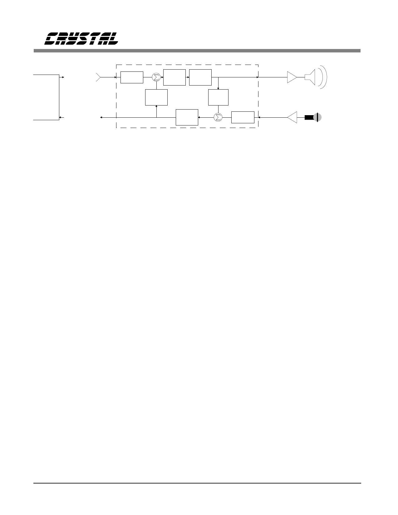
Figure 3. Functional Diagram
Near-End Output
AAAAAAAAAAAAAAAAAAAAAAAAAAAAAAAAAAAAAAAAAAAAAAAAAAAAAAAA
Near-End Input
The Central Processing Unit (CPU) does all the
other miscellaneous processing, like update con-
trol and double talk detection. This processing
has a critical influence on overall echo-cancella-
tion performance. Double-talk detection is a
particularly important part of this processing.
Double-talk detection and other algorithms were
carefully developed and validated at Crystal un-
der real-world conditions.
To increase the CS6403’s echo return-loss en-
hancement (ERLE), supplemental echo
suppression is used. A sophisticated voice-detec-
tion algorithm is used to reduce echo with
minimal impact on conversation quality, assuring
the highest quality conversation.
Figure 3 describes the functional behavior of the
CS6403 in a typical application. Digital data
from the far-end interface comes into SDI of the
CS6403 where it is acted upon by the various
algorithms running in the CPU. First, a High-
Pass Filter eliminates DC offset and low
frequency noise before sending the far-end input
data onto the summing node for the network
echo canceller. Assuming there is no speech
from the near-end, the signal after the summing
node is unaffected.
The signal then passes on to the AGC/Volume
Control block where the signal level is boosted,
if necessary. The volume control is implemented
in part by the AGC (for more details, see the
section entitled "Embedded Signal Processing
Functions").
10
The signal then passes on to the Non-linear Echo
Control block which controls the half-duplex
failsafe and the supplementary echo suppressor
which act to enhance and supplement the per-
formance of the echo canceller.
The signal after this block is then fed to both the
speaker output and the input to the acoustic echo
canceller (implemented by the AFP). The
speaker output couples to the microphone input
by various echo paths. The signal received at
the microphone is then filtered and sent on to the
summing node of the Acoustic Echo Canceller.
The Acoustic Echo Canceller constructs a model
of the echo paths between the speaker and mi-
crophone and processes its input signal with its
digital representation of the echo paths. As such,
its output should very closely match the input
from the microphone and so the output from the
summing node should be a very small signal,
which is referred to as the "error signal." This
error signal is fed back to the echo canceller to
let it adapt its performance should there be a
change in the echo path.
The Non-linear Echo Control block following
the summing node further attenuates any vestiges
of signal received at the microphone that origi-
nated from the speaker. This signal is then sent
to the far-end output by SDO as well as to the
input of the Network Echo Canceller, where a
function similar to that performed by the Acous-
tic Echo Canceller is performed.
DS192PP6
Share Link: 