AS1324 データシートの表示(PDF) - austriamicrosystems AG
部品番号
コンポーネント説明
一致するリスト
AS1324 Datasheet PDF : 21 Pages
| |||
AS1324
Datasheet - Application Information
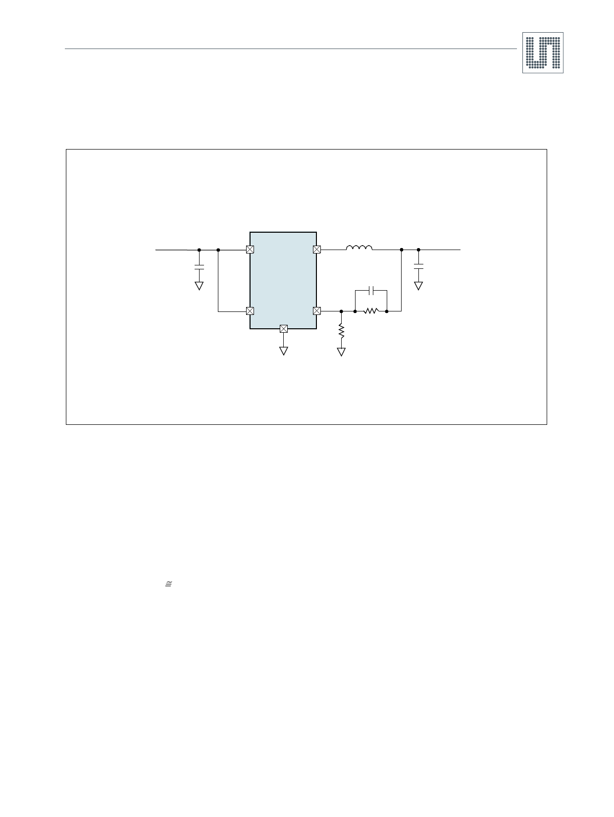
9.9 Design Example
Figure 28 shows the AS1324 used in a single lithium-ion (3.7V typ) battery-powered mobile phone application. The load current requirement is
600mA (max) but most of the time the device will require only 2mA (standby mode current).
Figure 28. Design Example
VIN
3.7V
CIN
4.7µF
CER
4
3
2.2µH
VIN
SW
AS1324
22pF
1
5
1MΩ
EN
VFB
R2
2 GND
R1 375kΩ
COUT
10µF
CER
VOUT
2.2V
For the circuit shown in Figure 28, efficiency at low- and high-load currents is an important consideration when selecting the value for the
external inductor, which is calculated as:
L
=
V-----O----U---T--
f∆IL
×
1
–
V---V--O---I-UN----T-
(EQ 14)
From (EQ 14), substituting VOUT = 2.2V, VIN = 3.7V, ∆IL = 240mA and f = 1.5MHz gives:
L
=
(---1---,--5----M-----H---2--z--,-2-×---V--2---4----0---m------A----)-
×
1
–
3-2---,,--27---VV---
=
2,48µH
(EQ 15)
Therefore, a standard 2.2µH inductor should be used for this design.
For best overall efficiency use an inductor with a rating of 720mA or greater and less than 0.2Ω series resistance. CIN will require an RMS
current rating of at least 0.3A ≅ ILOAD(MAX)/2, whereas COUT will require an ESR of less than 0.25Ω. In most cases, a ceramic capacitor will
satisfy this requirement.
For the feedback resistors, select the value for R1 = 375kΩ. R2 can then be calculated from (EQ 7) to be:
R2 = (VOUT/0.6 - 1)375k = 1000kΩ
www.ams.com/DC-DC_Step-Up/AS1324
Revision 1.06
15 - 21
Share Link: 