AS1324 データシートの表示(PDF) - austriamicrosystems AG
部品番号
コンポーネント説明
一致するリスト
AS1324 Datasheet PDF : 21 Pages
| |||
AS1324
Datasheet - Application Information
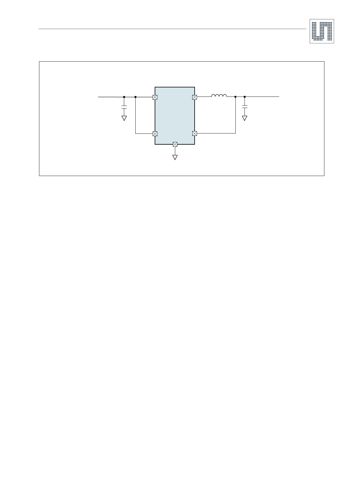
Figure 25. Single Li-Ion 1.8V/600mA Regulator for Low Output Ripple
VIN
2.7 to 4.2V
CIN
10µF
4.7µH
4
3
VIN
SW
AS1324-18
1
5
EN
VOUT
2 GND
COUT
22µF
VOUT
1.8V
600mA
9.1 External Component Selection
9.2 Inductor Selection
For most applications the value of the external inductor should be in the range of 2.2 to 6.8µH as the inductor value has a direct effect on the
ripple current. The selected inductor must be rated for its DC resistance and saturation current. The inductor ripple current (∆IL) decreases with
higher inductance and increases with higher VIN or VOUT.
In Equation (EQ 2) the maximum inductor current in PWM mode under static load conditions is calculated. The saturation current of the inductor
should be rated higher than the maximum inductor current as calculated with Equation (EQ 3). This is recommended because the inductor
current will rise above the calculated value during heavy load transients.
∆IL = VOUT × -1----–--L---V----×--V---O-----fI---U-N------T---
(EQ 2)
ILMAX
=
IOUTMAX
+
∆----I--L-
2
Where:
f = Switching Frequency (1.5 MHz typical)
L = Inductor Value
ILmax = Maximum Inductor current
∆IL = Peak to Peak inductor ripple current
The recommended starting point for setting ripple current is ∆IL = 240mA (40% of 600mA).
(EQ 3)
The DC current rating of the inductor should be at least equal to the maximum load current plus half the ripple current to prevent core saturation.
Thus, a 720mA rated inductor should be sufficient for most applications (600mA + 120mA). A easy and fast approach is to select the inductor
current rating fitting to the maximum switch current limit of the converter.
Note: For highest efficiency, a low DC-resistance inductor is recommended.
Accepting larger values of ripple current allows the use of low inductance values, but results in higher output voltage ripple, greater core losses,
and lower output current capability.
The total losses of the coil have a strong impact on the efficiency of the dc/dc conversion and consist of both the losses in the dc resistance and
the following frequency-dependent components:
1. The losses in the core material (magnetic hysteresis loss, especially at high switching frequencies)
2. Additional losses in the conductor from the skin effect (current displacement at high frequencies)
3. Magnetic field losses of the neighboring windings (proximity effect)
4. Radiation losses
www.ams.com/DC-DC_Step-Up/AS1324
Revision 1.06
11 - 21
Share Link: 