MAX9546 データシートの表示(PDF) - Maxim Integrated
部品番号
コンポーネント説明
一致するリスト
MAX9546 Datasheet PDF : 17 Pages
| |||
MAX9546/MAX9547
Differential Video Interface Chipset
Common-Mode Balance
A driver is typically specified as having a property called
common-mode balance (CMB), longitudinal balance, or
simply line imbalance. Although balance is associated
with the source, it assumes a perfectly balanced, correctly
terminated, differential load. Common-mode balance
is a measure of the ratio between the differential to the
common-mode output in decibels as shown below.
CMB
=
20Log
(OUT
(OUT
+)
+)
−
+
(OUT
(OUT
−)
−)
2
Common-mode balance is dominated by the gain-band-
width product at high frequencies and the output resis-
tance at low frequencies; therefore, it is important to
specify CMB over a frequency range. The receiver-side
balance is determined by the common-mode rejection
ratio (CMRR). The CMRR is usually quite large compared
to the CMB; therefore, the CMB is the limiting factor.
Fault Protection and Detection
The MAX9546 fault protection insures the driver outputs
survive a short to any voltage from -2V to +16V and are
ESD-protected to ±15kV HBM. Faults are indicated by an
open-drain fault output (FAULT) being asserted low and
requires a pullup resistor from FAULT to VCC.
MAX9547
Receiver
The MAX9547 receiver is a differential-to-single-ended con-
verter that removes any common-mode input. The unique
architecture allows the signal gain to be set by a ratio of
two impedances: the user-selected transconductance ele-
ment or network (ZZT), and an output load resistance, RL.
The gain is set by a fixed internal current gain (K) and the
ratio of ZZT and RL. The ZT terminals can be bridged with
a complex impedance to provide lead-lag compensation.
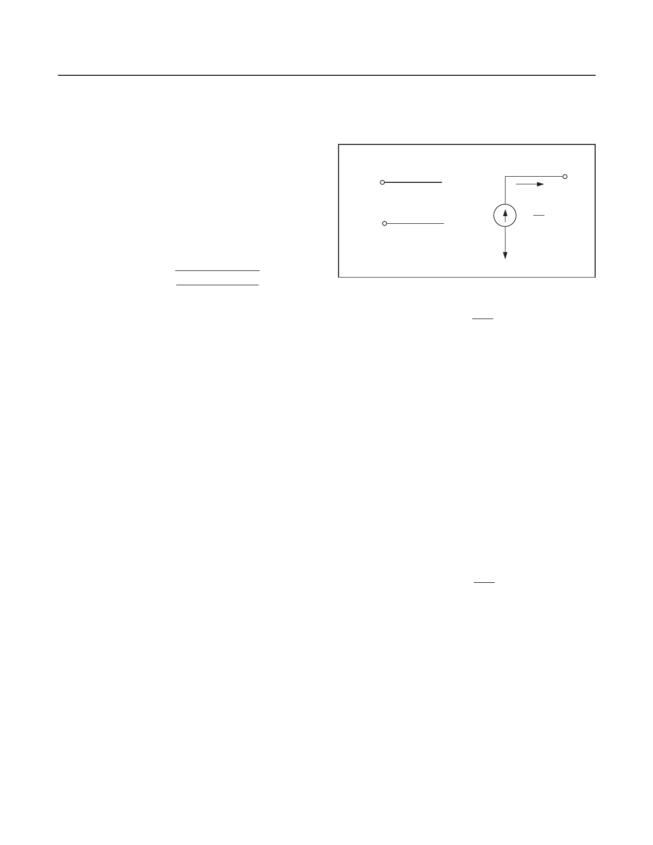
The output is essentially a voltage-controlled current source
as shown in Figure 1. The MAX9547 output is a current
proportional to the differential input voltage, and inversely
proportional to the impedance of the user-selected trans-
conductance network, ZZT. The current output provides
inherent short-circuit protection for the output terminal.
A differential input voltage applied to the input terminals
causes current to flow in the transconductance element
(ZZT), which is equal to VIN/ZZT. This current in the trans-
conductance element is multiplied by the preset current
gain (K) and appears on the output terminal as a current
equal to (K) x (VIN/ZZT). This current flows through the load
impedance to produce an output voltage according to the
following equation:
IN+
1
+
VIN
IN-
-
4
7
IOUT
K
VIN ZZT
Figure 1. Operational Mode
VOUT
=
K
VIN
Z ZT
RL
where K = current-gain ratio (K = 1 for MAX9547), RL =
output load impedance, ZZT = transconductance element
impedance, VIN = differential input voltage.
Loss-of-Signal
The receiver includes an LOS output to indicate a signal
by detecting the presence of H-Sync. This allows the
MAX9547 to be used with monochrome or color video.
LOS is an open-drain output and requires a pullup resistor
from LOS to VCC.
Setting the Circuit Gain
The MAX9547 produces an output current by multiplying
the differential input voltage, VIN, by the transconduc-
tance ratio, K (RL / ZZT), where K = 1. The voltage gain
(AV) is set by the impedance of the transconductance net-
work (ZZT) and the output load impedance (RL) according
to the following formula:
AV
=
K
RL
Z ZT
The factor ZZT is the impedance of the user-selected, two-
terminal transconductance element or network, connected
across the terminals labeled ZT+ and ZT-. The network
ZZT is selected, along with the output impedance RL, to
provide the desired circuit gain and frequency shaping.
To maintain linearity, the transconductance network should
also be selected so that current flowing through it, equal
to VIN / ZZT, does not exceed 18mA under worst-case
conditions of maximum input voltage and minimum trans-
conductance element impedance (ZZT). Output current
should not exceed ±8.8mA except under fault conditions.
www.maximintegrated.com
Maxim Integrated │ 9
Share Link: 