MAX9546 データシートの表示(PDF) - Maxim Integrated
部品番号
コンポーネント説明
一致するリスト
MAX9546 Datasheet PDF : 17 Pages
| |||
MAX9546/MAX9547
Differential Video Interface Chipset
Applications Information
Differential Interface
The impedances of the differential interface are made
up of the two source resistors on the driver (MAX9546)
shown as RS and the load resistors on the receiver
(MAX9547) shown as RT in the Typical Application
Circuit. These resistors are chosen so their sum matches
the characteristic impedance (Z0) of the differential trans-
mission line. For example, a Category 5 cable has a char-
acteristic impedance of 110Ω, so the sum of the two RS
or RT resistors must be 110Ω to correctly drive the line.
To balance the signals they must be equal, so RS and RT
are 55Ω each.
Using Other Transmitters
and Receivers
The MAX9546/MAX9547 are used with other transmit-
ters and receivers; either other MAXIM devices or other
brands entirely. The overall performance of the MAX9546/
MAX9547 is dependent on the choice of the receiver or
transmitter, respectively.
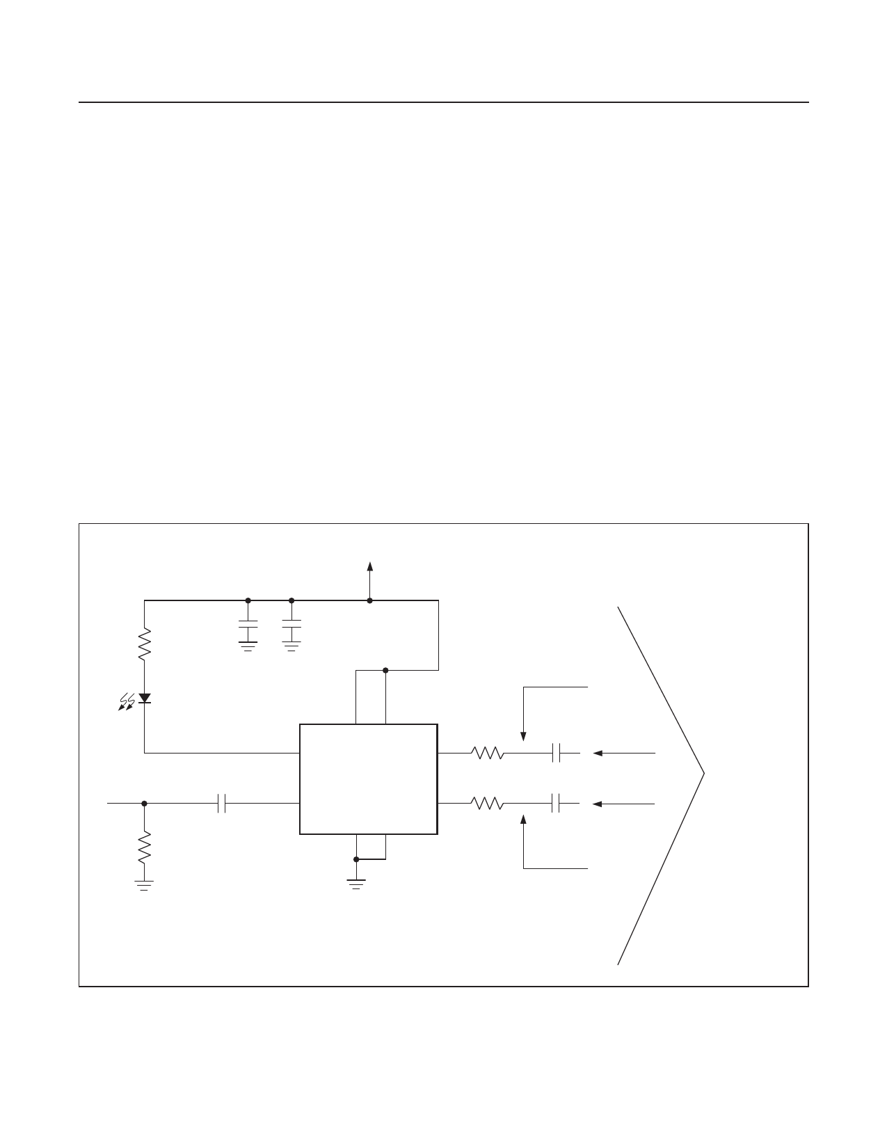
Figure 2 illustrates one possible topology for the MAX9546
when using other devices with different offset require-
ments. Figures 3 and 4 illustrate two possible topologies
for the MAX9547 when using other devices with unknown
or different offset requirements. The circuit shown in
Figure 3 has a smaller PCB footprint at the expense
of requiring higher DC offset currents from the source
device. Figure 4 requires no DC offset currents although
it has a larger PCB footprint.
When using the MAX9546 with AC-coupling capacitors,
the FAULT signal will continue to function but only with
respect to a DC short condition. The LOS signal from the
MAX9547 is unaffected by coupling capacitors.
VDD
R1
3.92kΩ
4.7µF
D1
C4
R4
0.33µF
75Ω
0.1µF
+3.2 VDC OFFSET
18
3 FAULT
VCC VCC
OUT+ 7
R2
55Ω
U1
MAX9546
2 IN
OUT- 6
R3
GND GND
55Ω
4
5
C3
470µF
C5
470µF
0V OFFSET
+3.2 VDC OFFSET
TO A DEVICE
OTHER THAN A
MAX9547 USING
CAT5, ETC.
Figure 2. Suggested MAX9546 Configuration for Use with Other Devices
www.maximintegrated.com
Maxim Integrated │ 10
Share Link: 