NJU3101 データシートの表示(PDF) - Japan Radio Corporation
部品番号
コンポーネント説明
一致するリスト
NJU3101 Datasheet PDF : 22 Pages
| |||
NJU3101
s CLOCK GENERATION
The system clock is generated in the internal oscillator circuit with the external crystal or ceramic resonator,
or the resistor connected to OSC1 and OSC2 terminals. Furthermore, the NJU3101 can operate by the
external clock to the OSC1 terminal for the system clock. In the external clock operation, the OSC2 terminal
must be opened.
The typical application examples for each oscillator circuit are shown in follows. However a Crystal or a
Ceramic operation requires the considered evaluation, because the oscillator operates in accordance with the
characteristics of each component.
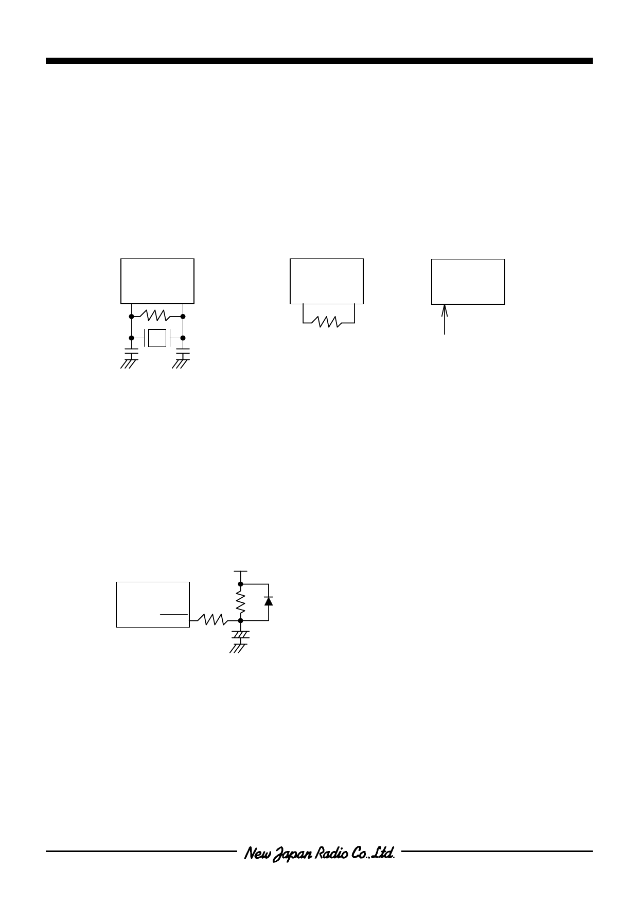
[OSCILLATOR APPLICATION EXAMPLES]
1) X’tal/Ceramic oscillation
2) CR oscillation
3) External clock input
NJU3101
OSC1
OSC2
Rf*
NJU3101
OSC1 OSC2
NJU3101
OSC1 OSC2
External clock
The resistor Rf* is
sometimes required to
connect when the Crystal
operation.
s RESET OPERATION
All of the internal circuits are initialized by inputting the low level signal to the RESET terminal.
A circuit example for Power On Reset Operation with a resistor, a capacitor, and a diode is shown in bellow.
Power On Reset Operation requires to keep the low level of the input signal to RESET terminal until the
stabilized oscillation of the internal oscillator. Therefore the constants on the reset circuit must be decided in
accordance with the characteristics of the clock generator circuit.
[An example of Power On Reset circuit]
VDD
NJU3101
R*
RESET
R*:A resistor as RESET terminal protector. It is required depending on the condition of an application.
- 14 -
Share Link: 