NJU3101 データシートの表示(PDF) - Japan Radio Corporation
部品番号
コンポーネント説明
一致するリスト
NJU3101 Datasheet PDF : 22 Pages
| |||
NJU3101
s STANDBY FUNCTION
STANDBY FUNCTION halts the IC operation and reduces the current consumption.
The STANDBY function starts by the HLT instruction. After the HLT instruction execution cycle, the internal
oscillator operation is stopped and all of the operation is halted. In case of the external clock operation, the
clock is stopped automatically delivering into the internal system by the internal circuit, and all of the operation
is halted as same as the internal oscillator operation. This is STANDBY mode.
In the STANDBY mode, the operating current can be reduced. Though the clock into the internal system is
stopped and all of the operation is halted, all conditions of Program Counter, Registers, and data in RAM are
kept certainly.
Two ways to release from the STANDBY mode are prepared. One way is the reset operation that when the
reset signal is input to RESET terminal, the operation starts from the initial condition. The other way is the
re-start operation that when the restart signal is input to PD0 terminal, the operation starts from the kept
Program Counter location which is the program address after the final operation. In case of the restart signal
operation, if the rising signal, low to high, is input to PD0 terminal, the internal oscillator circuit starts at first.
After the stabilized clock from the internal oscillator was counted eight times, the clock is started delivering into
the internal system. Then the NJU3101 starts to operate from the kept Program Counter location with all of
the kept conditions.(See *1)
In case of the external clock operation, the external clock must be started to supply to the OSC1 terminal
before the STANDBY mode is released. The external clock is recommended to stop supplying to the OSC1
terminal for reducing the power consumption during the STANDBY mode.
*1: When the restart signal is input to PD0 terminal to release the STANDBY mode, PORTD must be selected
as the input by the mask option.
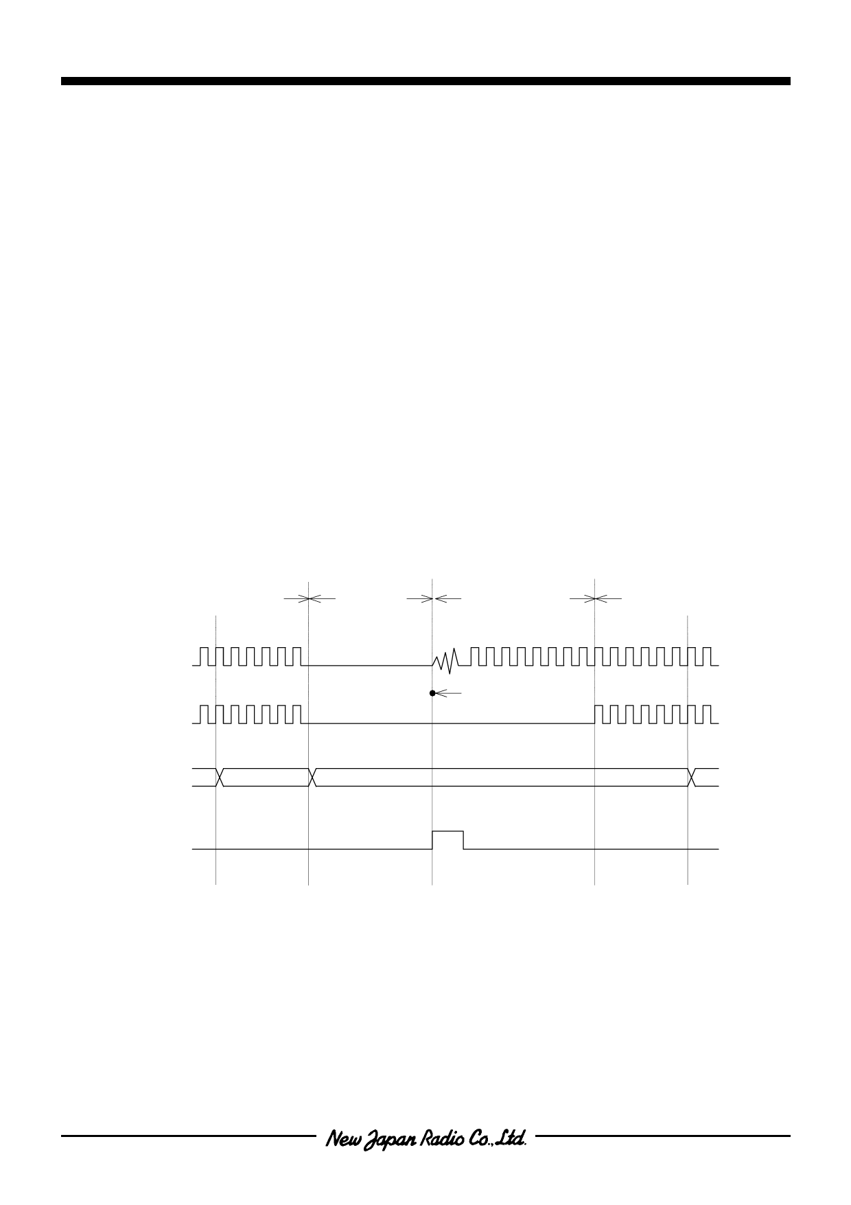
[STANDBY MODE TIMING CHART]
Normal
Operation
Oscillator
Clock
System
Clock
Execute
HLT
Instruction
Restart Signal
(PD0terminal)
STANDBY
Mode
Oscillation
Stability Time
Oscillation Start
next instruction
Normal
Operation
- 13 -
Share Link: 