CS61884 データシートの表示(PDF) - Cirrus Logic
部品番号
コンポーネント説明
一致するリスト
CS61884 Datasheet PDF : 71 Pages
| |||
CS61884
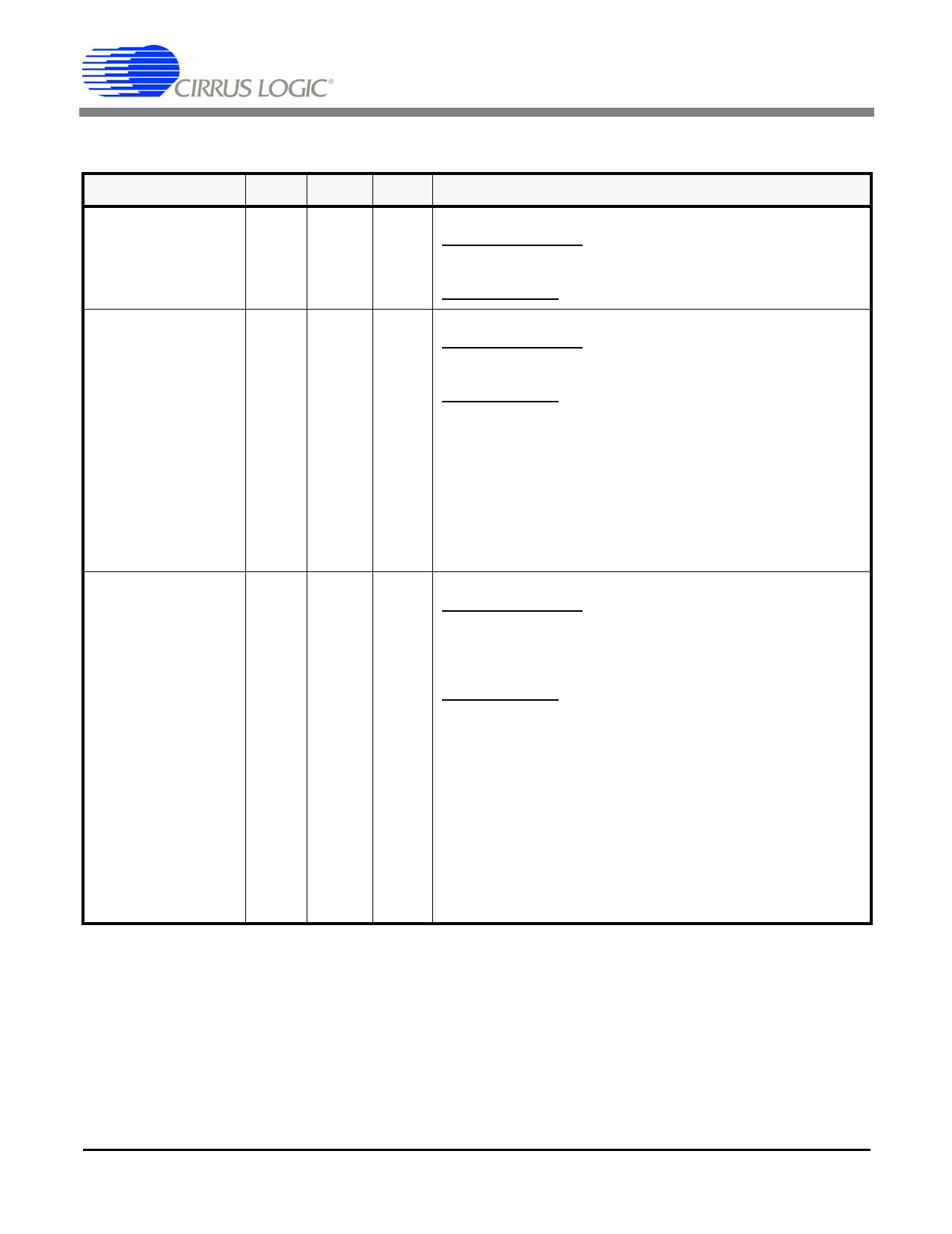
3.3 Address Inputs/Loopbacks
SYMBOL
A4
A3
A2
A1
A0
LOOP0/D0
LOOP1/D1
LOOP2/D2
LOOP3/D3
LOOP4/D4
LOOP5/D5
LOOP6/D6
LOOP7/D7
LQFP FBGA TYPE
DESCRIPTION
12
F4
Address Selector Input
Parallel Host Mode - During non-multiplexed parallel host
I mode operation, this pin function as the address 4 input for
the parallel interface.
Hardware Mode - The A4 pin must be tied low at all times.
13
F3
14
F2
15
F1
16
G3
Non-Intrusive Monitoring/Address Selector Inputs
Parallel Host Mode - During non-multiplexed parallel host
mode operation, these pins function as address A[3:0] in-
puts for the parallel interface.
Hardware Mode - The A[3:0] pins are used for port selec-
I tion during non-intrusive monitoring. In non-intrusive
monitoring mode, receiver 0’s input is internally connected
I
to the transmit or receive ports on one of the other 7 chan-
nels. The recovered clock and data from the selected port
I
are output on RPOS0/RNEG0 and RCLK0. Additionally, the
data from the selected port can be output on
I
TTIP0/TRING0 by activating the remote loopback function
for channel 0 (Refer to Performance Monitor Register
(0Bh) (See Section 14.12 on page 36).
Loopback Mode Selector/Parallel Data Input/Output
Parallel Host Mode - In non-multiplexed microprocessor in-
21
G2
I/O terface mode, these pins function as the bi-directional 8-bit
data port. When operating in multiplexed microprocessor in-
22
H3
I/O terface mode, these pins function as the address and data
inputs/outputs.
23
H2
I/O Hardware Mode
- No Loopback - The CS61884 is in a normal operating
24
J4
I/O state when LOOP is left open (unconnected) or tied to
VCCIO/2.
25
J3
I/O
- Local Loopback - When LOOP is tied High, data transmit-
ted on TTIP and TRING is looped back into the analog
26
J2
I/O
input of the corresponding channel’s receiver and output on
RPOS and RNEG. Input Data present on RTIP and RRING
is ignored.
27
J1
I/O - Remote Loopback - When LOOP is tied Low the recov-
ered clock and data received on RTIP and RRING is looped
28
K1
I/O back for transmission on TTIP and TRING. Data on TPOS
and TNEG is ignored.
14
DS485F1
Share Link: 