ZR36067 データシートの表示(PDF) - Unspecified
部品番号
コンポーネント説明
一致するリスト
ZR36067 Datasheet PDF : 48 Pages
| |||
AV PCI CONTROLLER
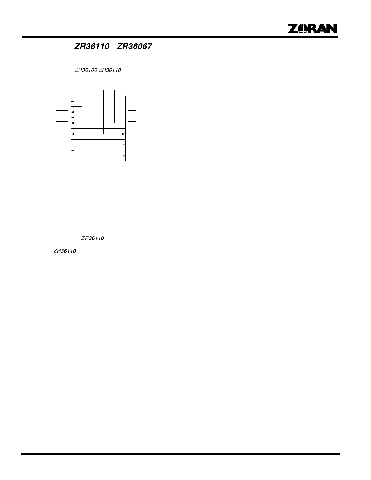
Appendix A: ZR36110 - ZR36067 Interface
Figure 15 describes a recommended interconnection between
the ZR36067 and the ZR36100/ZR36110 host bus.
ZR36100/110
DREQ
DACK
BUSCS
BUSWR
BUSRD
BUSADD[1:0]
BUSDAT[7:0]
READY
IDLE
RESET
VSYNC
Other Guests
VDD
ZR36067
(Optional)
(Optional)
GCSn
GWR
GRD
GADR[2:0]
GDAT[7:0]
GRDY
GIRQ0
GPIO0
GIRQ1
Figure 15. ZR36067 - ZR36100/110 Basic Interconnection
ZR36110 Reset
Any of the software controlled GPI/O pins (configured as output)
of the ZR36067 may be used as a RESET input of the decoder.
The software then directly manipulates the RESET signal
through the corresponding register bit. Since the default config-
uration of the GPIO pins after reset is input, a pull down resistor
should be applied to the ZR36110 RESET input.
Mapping the ZR36110 on the ZR36067’s GuestBus
The driver software must map the ZR36110 on the GuestBus:
the ZR36110’s guest ID number (0,1,2, or 3) must be configured
as a code-write target. The proper timing parameters (tdur = 3,
to ensure 82ns, trec = 4, to ensure 100ns) of the ZR36110 must
be loaded to the GuestBus control register (address 0x030). The
ZR36110 occupies only four 8-bit registers out of the eight reg-
isters dedicated to each guest.
ZR36110 Initialization
The initialization consists of loading the ZR36110 microcodes
and parameters. This is done using the PostOffice mechanism.
The host interface of the ZR36110 must be set to 8 bit, Intel
format, I/O only. The BSLN parameter should be set to 2 or 4, for
efficient operation.
On-Line Commands and Status
On-line command writes and status reads are also done using
the PostOffice mechanism.
Bitstream Transfer
Some preparations must be done prior to triggering the
ZR36110 with a go command.
The host must allocate a contiguous code buffer in the system
memory. Bitstream retrieved from the MPEG source is stored in
this buffer. The ZR36067 reads data from this buffer in a DMA
fashion and transfers it, through the CFIFO, to the MPEG
decoder. There are several possible sizes of the memory buffer.
The host must inform the ZR36067 of the buffer address, size
and “report step”. After the code buffer in memory is allocated,
reported to the ZR36067, and filled up for the first time, a
ZR36110 go command can be issued. Immediately after this, the
DMA code-read cycles must be enabled by setting the DMA
Code-Read Enable bit to ‘1’. The ZR36067 then starts fetching
data from the main memory buffer using cyclic addressing.
Whenever it passes a “report step” it initializes an interrupt
request. Within the interrupt service routine the host should
check the current position of the ZR36067 Code Memory Buffer
Pointer, and decide weather it should refresh an old portion of
the buffer with new data from the MPEG source. Once the coded
data arrives at the CFIFO, the GBM unit starts writing it over the
GuestBus to the ZR36110.
44
Share Link: 