PCA1461 データシートの表示(PDF) - NXP Semiconductors.
部品番号
コンポーネント説明
一致するリスト
PCA1461 Datasheet PDF : 24 Pages
| |||
Philips Semiconductors
32 kHz watch circuits with adaptive motor
pulse
Product specification
PCA146x series
Voltage level detector
The supply voltage is compared with the internal voltage
reference VLIT and VEOL every minute. The first voltage
level detection is carried out 30 ms after RESET.
When a lithium voltage level is detected (VDD ≥ VLIT), the
circuit starts operating in the lithium mode (Fig.4).
When the detected VDD voltage level is between VLIT and
VEOL, the circuit operates in the silver-oxide mode (Fig.3).
If the battery end-of-life is detected (VDD < VEOL), the
detection and stage control is switched OFF and the
waveform produced is an unchopped version of the
stage 8 waveform. To indicate this condition the waveform
is produced in bursts of 4 pulses every 4 s.
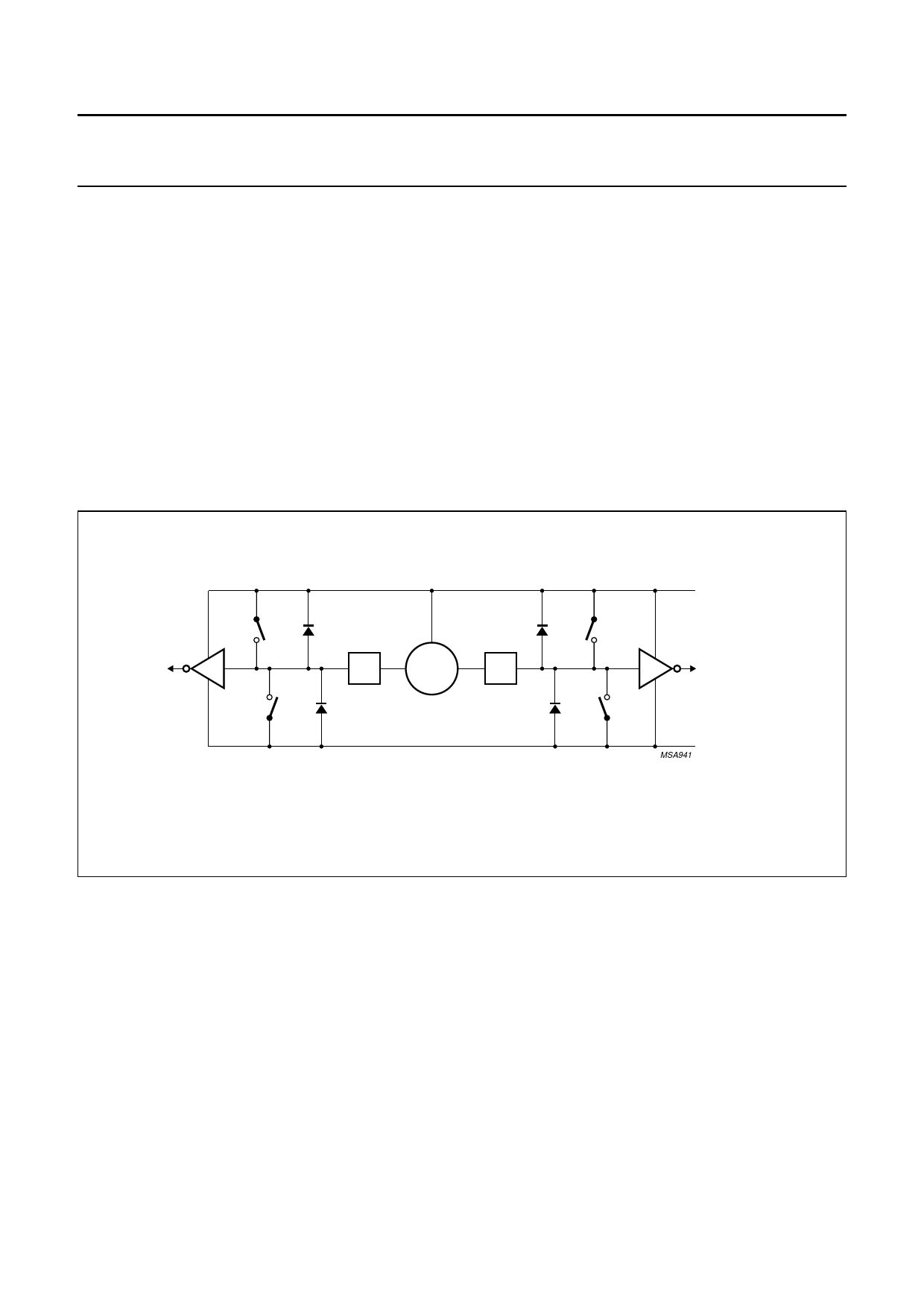
Detection of motor movement
After a motor pulse, the motor is short-circuited to VDD for
1 ms. Afterwards the energy in the motor inductor will be
dissipated to measure only the current generated by the
induced motor voltage. During the time tDI (dissipation of
energy time) all switches shown in Fig.5 are open to
reduce the current as fast as possible. The current will now
flow through the diodes D3 and D2, or D4 and D1. Then
the first of 52 possible measurement cycles (tMC) starts to
measure the induced current.
P1
D1
D2
P2
VDD
L1
M1
MOTOR
M2
L2
N1
D3
D4
N2
V SS
MSA941
Fig.5 Motor driving and detecting circuit.
1998 Apr 21
7
Share Link: 