PCA1461 データシートの表示(PDF) - NXP Semiconductors.
部品番号
コンポーネント説明
一致するリスト
PCA1461 Datasheet PDF : 24 Pages
| |||
Philips Semiconductors
32 kHz watch circuits with adaptive motor
pulse
Product specification
PCA146x series
Time calibration
Taking a normal quartz crystal with frequency 32768kHz,
frequency deviation (∆f/f) of ±15 × 10−6 and CL = 8.2 pF;
the oscillator frequency is offset (by using non-symmetrical
internal oscillator input and output capacitances of 10 pF
and 15 pF) such that the frequency deviation is
positive-only. This positive deviation can then be
compensated for to maintain time-keeping accuracy.
Once the positive frequency deviation is measured, a
corresponding number ‘n’ (see Table 2) can be
programmed into the device’s EEPROM. This causes n
pulses of frequency 8192 Hz to be inhibited every minute
of operation, which achieves the required calibration.
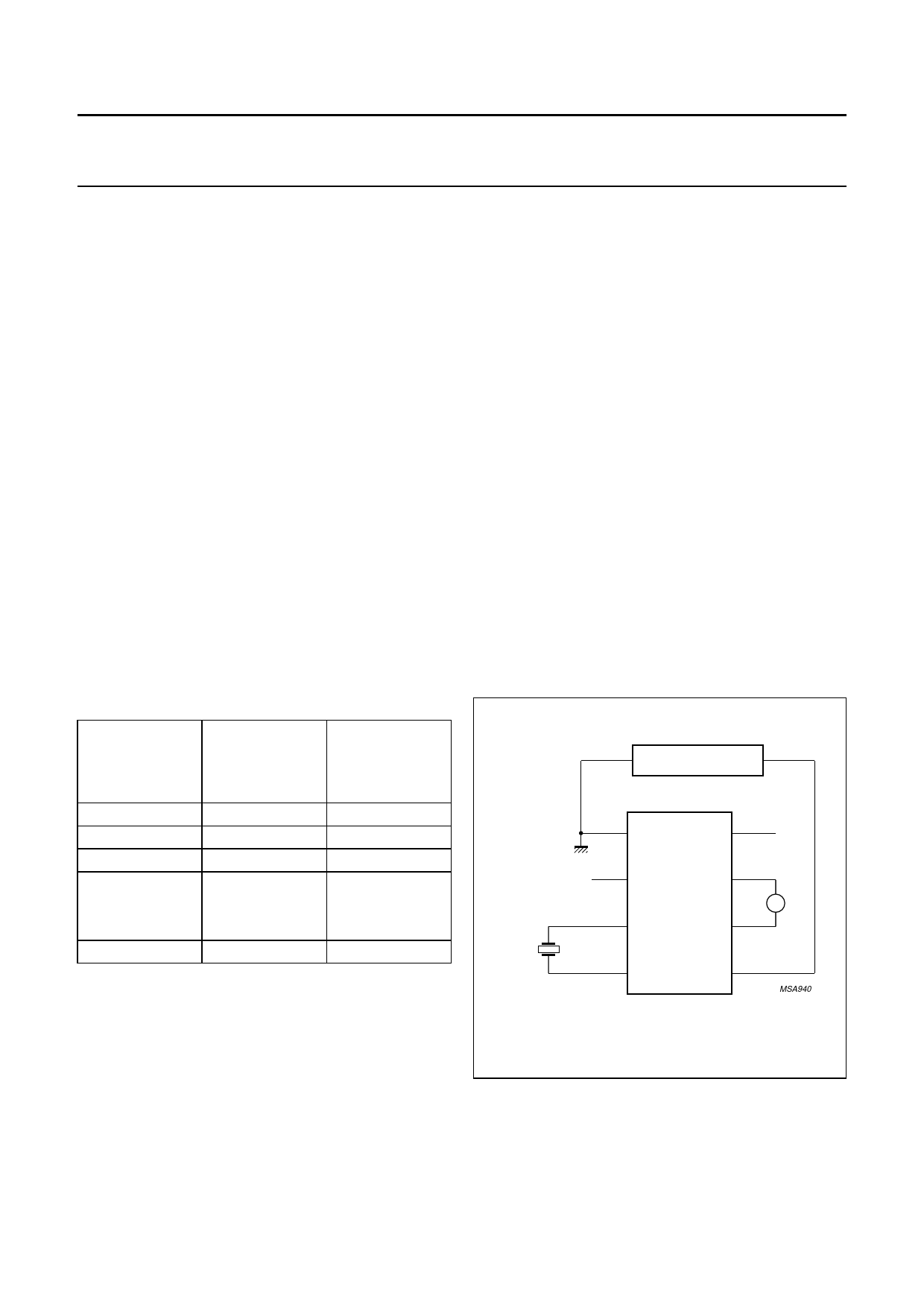
The programming circuit is shown in Fig.9. The required
number n is programmed into EEPROM by varying VDD
according to the steps shown in Fig.10, which are
explained below:
1. The positive quartz frequency deviation (∆f/f) is
measured, and the corresponding values of n are
found according to Table 2.
2. VDD is increased to 5.1 V allowing the contents of the
EEPROM to be checked from the motor pulse period
tT3 at nominal frequency.
3. VDD is decreased to 2.5 V during a motor pulse to
initialize a storing sequence.
4. The first VDD pulse to 5.1 V erases the contents of
EEPROM.
5. When the EEPROM is erased a logic 1 is at the TEST
pin.
6. VDD is increased to 5.1 V to read the data by pulsing
VDD n times to 4.5 V. After the n edge, VDD is
decreased to 2.5 V.
7. VDD is increased to 5.1 V to store n bits in the
EEPROM.
8. VDD is decreased to 2.5 V to terminate the storing
sequence and to return to operating mode.
9. VDD is increased to 5.1 V to check writing from the
motor pulse period tT3.
10. VDD is decreased to the operation voltage between
two motor pulses to return to operating mode.
(Decreasing VDD during the motor pulse would restart
the programming mode).
The time calibration can be reprogrammed up to 100
times.
Table 2 Quartz crystal frequency deviation, n and tT3
FREQUENCY
DEVIATION
∆f/f
(× 10−6)
0(1)
+2.03
+4.06
.
.
.
+127.89
NUMBER OF
PULSES
(n)
0
1
2
.
.
.
63
tT3
(ms)
31.250(2)
31.372
31.494
.
.
.
38.936
Notes
1. Increments of 2.03 × 10⁻⁶/step.
2. Increments of 122 µs/step.
SIGNAL GENERATOR
32 kHz
V SS
1
RESET
8
TEST
2
M2
7
PCA146x
SERIES
M
OSC IN
M1
3
6
OSC OUT
4
VDD
5
MSA940
Fig.9 Circuit for programming the time calibration.
1998 Apr 21
11
Share Link: 