NJU3502L データシートの表示(PDF) - Japan Radio Corporation
部品番号
コンポーネント説明
一致するリスト
NJU3502L Datasheet PDF : 42 Pages
| |||
NJU3502
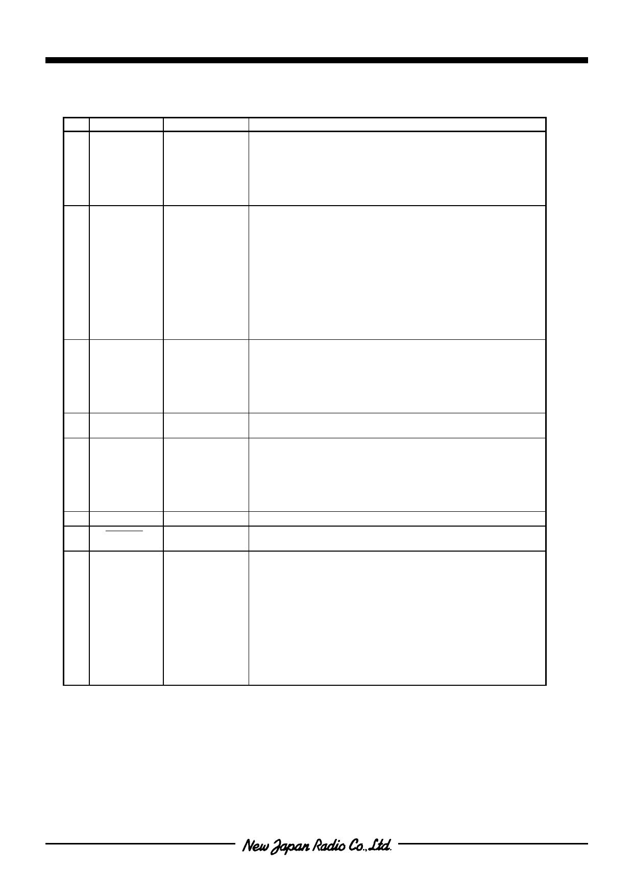
s TERMINAL DESCRIPTION 1
No. SYMBOL INPUT/OUTPUT
FUNCTION
22
PC0
INPUT/OUTPUT 4-bit Input / Output PORTC.
23
PC1
INPUT/OUTPUT Selects a terminal circuit for each port from follows by the
1
PC2
INPUT/OUTPUT mask option.
2
PC3
INPUT/OUTPUT • C-MOS Input Terminal with Pull-up Resistance(IA)
• C-MOS Input Terminal(IC)
• C-MOS Output Terminal(OB)
3
PD0
INPUT/OUTPUT 2-bit Input / Output PORTD.
4
PD1
INPUT/OUTPUT Selects a terminal circuit for each port from follows by the
mask option.
• C-MOS Schmitt Trigger Input Terminal with
Pull-up Resistance(IB)
• C-MOS Schmitt Trigger Input Terminal(ID)
• C-MOS Output Terminal(OB)
When the ports are selected as the input terminal, PD0
operates also as RESTART signal input terminal to return
from STANDBY mode, and PD1 operates also as the Edge
Detector Terminal.
5
PA0
INPUT/OUTPUT 4-bit Input / Output PORTA.
6
PA1
INPUT/OUTPUT Selects a terminal circuit for each port from follows by the
7
PA2
INPUT/OUTPUT mask option.
8
PA3
INPUT/OUTPUT • C-MOS Input Terminal with Pull-up Resistance(IA)
• C-MOS Input Terminal(IC)
• C-MOS Output Terminal(OB)
9
TEST
INPUT
Maker Testing Terminal with Pull-down Resistance
The terminal is recommended to connect to GND.
10
OSC1
INPUT
Internal Oscillator Terminals.
11
OSC2
OUTPUT Connects a device selected from the ceramic or the crystal
resonator, or the resistor, to these terminals for the internal
oscillator.
In the external clock operation, OSC1 is the external clock
input terminal and OSC2 is normally open terminal.
12
VSS
13
RESET
–
INPUT
Power Source (0V)
RESET Terminal.
When the low level input-signal, the system is initialized.
14 EXTI / PE0
INPUT
1-bit Input PORTE.
Selects a function of either 1) or 2) for PORTE by the mask
option.
1) External Interrupt Input Terminal with Pull-up Resistance.
:EXTI
2) 1-bit Input Terminals as PORTE
Selects a terminal circuit for each port from follows by the
mask option.
• C-MOS Schmitt Trigger Input Terminal with
Pull-up Resistance(IB)
• C-MOS Schmitt Trigger Input Terminal(ID)
Note ) INPUT/OUTPUT : Input or Output is selected by the mask option.
INOUT
: Input or Output is changed by the program.
-3-
Share Link: 