MSM7718-01 データシートの表示(PDF) - Oki Electric Industry
部品番号
コンポーネント説明
一致するリスト
MSM7718-01 Datasheet PDF : 38 Pages
| |||
¡ Semiconductor
MSM7718-01
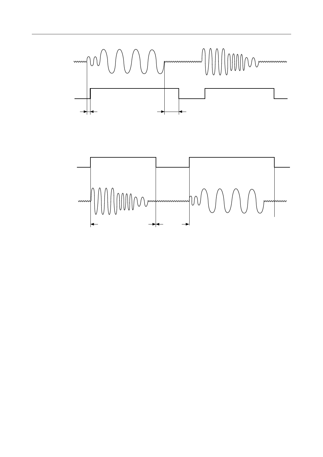
Voice Input
GSX2
VOXO
Voice
TVXON
Voice
Detect
Silence
Voice
TVXOFF
Silence
Detect (Hangover time)
(a) Transmit VOX Function Timing Diagram (for Analog Input)
VOXI
Voice
Silence
Voice
Voice Output
VFRO
Normal Voice Signal
Decoded Time Period
Background
Noise
(b) Receive VOX Function (CR6-B3: logic “0”) Timing Diagram (for Analog Input)
Note: The VOX function is valid when CR6-B7 is set to logic “1”.
Figure 6 VOX Function
MUTE
This pin is used to enable the receive side voice path mute level.
To set the mute level, set this pin to “1”.
MLV0, MLV1, MLV2
These pins are used to set the receive side voice path mute level.
For the control method, refer to the control register description (CR1). Since these pins are ORed
with CR1-B2, B1, and B0 internally, set the bits of the register to “0“ before using this pin.
12/38
Share Link: 