MKP1V120(2012) データシートの表示(PDF) - ON Semiconductor
部品番号
コンポーネント説明
一致するリスト
MKP1V120 Datasheet PDF : 5 Pages
| |||
MKP1V120 Series
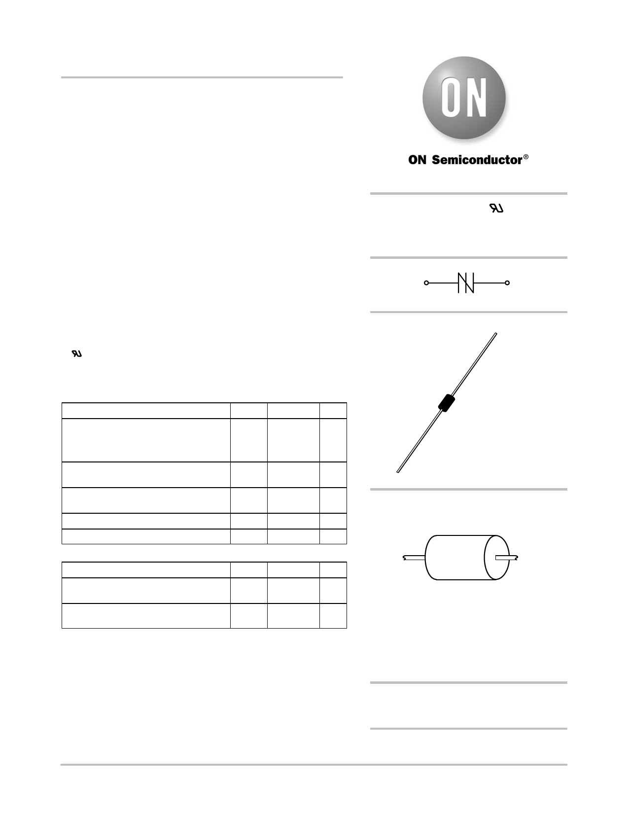
Sidac High Voltage
Bidirectional Triggers
Bidirectional devices designed for direct interface with the ac power
line. Upon reaching the breakover voltage in each direction, the device
switches from a blocking state to a low voltage on−state. Conduction
will continue like a Triac until the main terminal current drops below
the holding current. The plastic axial lead package provides high pulse
current capability at low cost. Glass passivation insures reliable
operation.
Features
• High Pressure Sodium Vapor Lighting
• Strobes and Flashers
• Ignitors
• High Voltage Regulators
• Pulse Generators
• Used to Trigger Gates of SCR’s and Triacs
• Indicates UL Registered − File #E210057
• These are Pb−Free Devices*
MAXIMUM RATINGS (TJ = 25°C unless otherwise noted)
Rating
Symbol Value
Unit
Peak Repetitive Off−State Voltage
VDRM,
V
(Sine Wave, 50 to 60 Hz, TJ = − 40 to 125°C) VRRM
MKP1V120, MKP1V130, MKP1V160
"90
MKP1V240
"180
On-State Current RMS (TL = 80°C,
IT(RMS)
"0.9
A
Lead Length = 3/8″, All Conduction Angles)
Peak Non−repetitive Surge Current
(60 Hz One Cycle Sine Wave, TJ = 125°C)
Operating Junction Temperature Range
Storage Temperature Range
ITSM
"4.0
A
TJ −40 to +125 °C
Tstg −40 to +150 °C
THERMAL CHARACTERISTICS
Characteristic
Thermal Resistance, Junction−to−Lead
Lead Length = 3/8″
Symbol
RqJL
Max
40
Unit
°C/W
Lead Solder Temperature
TL
(Lead Length w 1/16″ from Case, 10 s Max)
260
°C
Stresses exceeding Maximum Ratings may damage the device. Maximum
Ratings are stress ratings only. Functional operation above the Recommended
Operating Conditions is not implied. Extended exposure to stresses above the
Recommended Operating Conditions may affect device reliability.
*For additional information on our Pb−Free strategy and soldering details, please
download the ON Semiconductor Soldering and Mounting Techniques
Reference Manual, SOLDERRM/D.
http://onsemi.com
SIDACS( )
0.9 AMPERES RMS
120 − 240 VOLTS
MT1
MT2
AXIAL LEAD
CASE 59
STYLE 2
MARKING DIAGRAM
A
MKP
1Vxx0
YYWW G
G
A
= Assembly Location
MKP1Vxx0 = Device Number
x= 12, 13, 16 or 24
YY
= Year
WW
= Work Week
G
= Pb−Free Package
(Note: Microdot may be in either location)
ORDERING INFORMATION
See detailed ordering and shipping information on page 2 of
this data sheet.
© Semiconductor Components Industries, LLC, 2012
1
August, 2012 − Rev. 12
Publication Order Number:
MKP1V120/D
Share Link: 