MCP2140 データシートの表示(PDF) - Microchip Technology
部品番号
コンポーネント説明
一致するリスト
MCP2140
Microchip Technology

MCP2140 Datasheet PDF : 58 Pages
| |||
MCP2140
2.4 Host UART Interface
The Host UART interface communicates with the Host
Controller. This interface has eight signals associated
with it: TX, RX, RTS, CTS, DSR, DTR, CD and RI. Sev-
eral of these signals are locally generated (not passed
over the IR interface). The Host UART is a half-duplex
interface, meaning that the system is either transmitting
or receiving, but not both simultaneously.
Note 1: The MCP2140 generates several non-
data signals locally.
2: The MCP2140 emulates a 3-wire serial
connection (TXD, RXD and GND). The
transceiver’s Transmit Data (TXD),
Receive Data (RXD) signals, and the
state of the CD. RI and DTR input pins
are carried back and forth to the Primary
device.
3: The RTS and CTS signals are local
emulations.
2.4.1 BAUD RATE
The baud rate for the MCP2140 serial port (the TX and
RX pins) is fixed at 9600 baud when the device
frequency is 7.3728 MHz.
2.4.2 TRANSMITTING
When the controller sends serial data to the MCP2140,
the controller’s baud rate is required to match the baud
rate of the MCP2140’s serial port.
2.4.3 RECEIVING
When the controller receives serial data from the
MCP2140, the controller’s baud rate is required to
match the baud rate of the MCP2140’s serial port.
2.4.4 HARDWARE HANDSHAKING
There are three Host UART signals used to control the
handshaking operation between the Host Controller
and the MCP2140. They are:
• DSR
• RTS
• CTS
2.4.4.1 DSR
The DSR signal is used to indicate that a link has been
established between the MCP2140 and the Primary
Device. Please refer to Section 2.13, “How Devices
Connect”, for information on how devices connect.
2.4.4.2 RTS
The RTS signal indicates to the MCP2140 that the Host
Controller is ready to receive serial data. Once an IR
data packet has been received, the RTS signal will be
low for the received data to be transferred to the Host
Controller. If the RTS signal remains high, an IR link
timeout will occur and the MCP2140 will disconnect
from the Primary Device.
2.4.4.3 CTS
The MCP2140 generates the CTS signal locally due to
buffer limitations.
The MCP2140 uses a 64-byte buffer for incoming data
from the IR Host. Another 29-byte buffer is provided to
buffer data from the UART serial port. The MCP2140
can handle IR data and Host UART serial port data
simultaneously. A hardware handshaking pin (CTS) is
provided to inhibit the Host Controller from sending
serial data when the Host UART buffer is not available
(Figure 2-3). Figure 2-4 shows a flow chart for Host
UART flow control using the CTS signal.
Note:
When the CTS output signal goes high, the
UART FIFO will store up to 6 bytes. This is
to allow devices that have a slow response
time to a change on the CTS signal time to
stop sending additional data (such as a
modem).
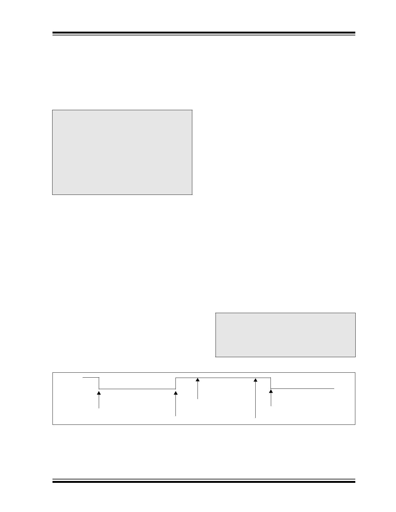
FIGURE 2-3:
HOST UART CTS SIGNAL AND THE RECEIVE BUFFER
CTS
Receive Buffer Empty
Receive Buffer
Full (29 Bytes)
IR Data Packet Transmitted
Receive Buffer Empty
MCP2140 Can Receive Data Receive Buffer Has 22 Bytes,
MCP2140 Can Receive Data
CTS Pin Driven High
IR Data Packet Starts Transmission
2003 Microchip Technology Inc.
Preliminary
DS21790A-page 9
Share Link: