MCP2140 データシートの表示(PDF) - Microchip Technology
部品番号
コンポーネント説明
一致するリスト
MCP2140
Microchip Technology

MCP2140 Datasheet PDF : 58 Pages
| |||
2.0 DEVICE OPERATION
The MCP2140 serial interface and IR baud rates are
fixed at 9600 baud, given a 7.3728 MHz device clock.
2.1 Power-Up
Any time the device is powered up (Parameter D003),
the Power-Up Timer delay (Parameter 33) occurs, fol-
lowed by an Oscillator Start-up Timer (OST) delay
(Parameter 32). Once these delays complete, commu-
nication with the device may be initiated. This commu-
nication is from both the infrared transceiver’s side and
the controller’s UART interface.
2.2 Device Reset
The MCP2140 is forced into the reset state when the
RESET pin is in the low state. Once the RESET pin is
brought to a high state, the Device Reset sequence
occurs. Once the sequence completes, functional
operation begins.
2.3 Device Clocks
The MCP2140 requires a clock source to operate. This
clock source is used to establish the device timing,
including the device “Bit Clock”.
2.3.1 CLOCK SOURCE
The clock source can be supplied by one of the
following:
• Crystal
• Resonator
• External clock
The frequency of this clock source must be
7.3728 MHz (electrical specification Parameter 1A) for
device communication at 9600 baud.
MCP2140
2.3.1.1
Crystal Oscillator / Ceramic
Resonators
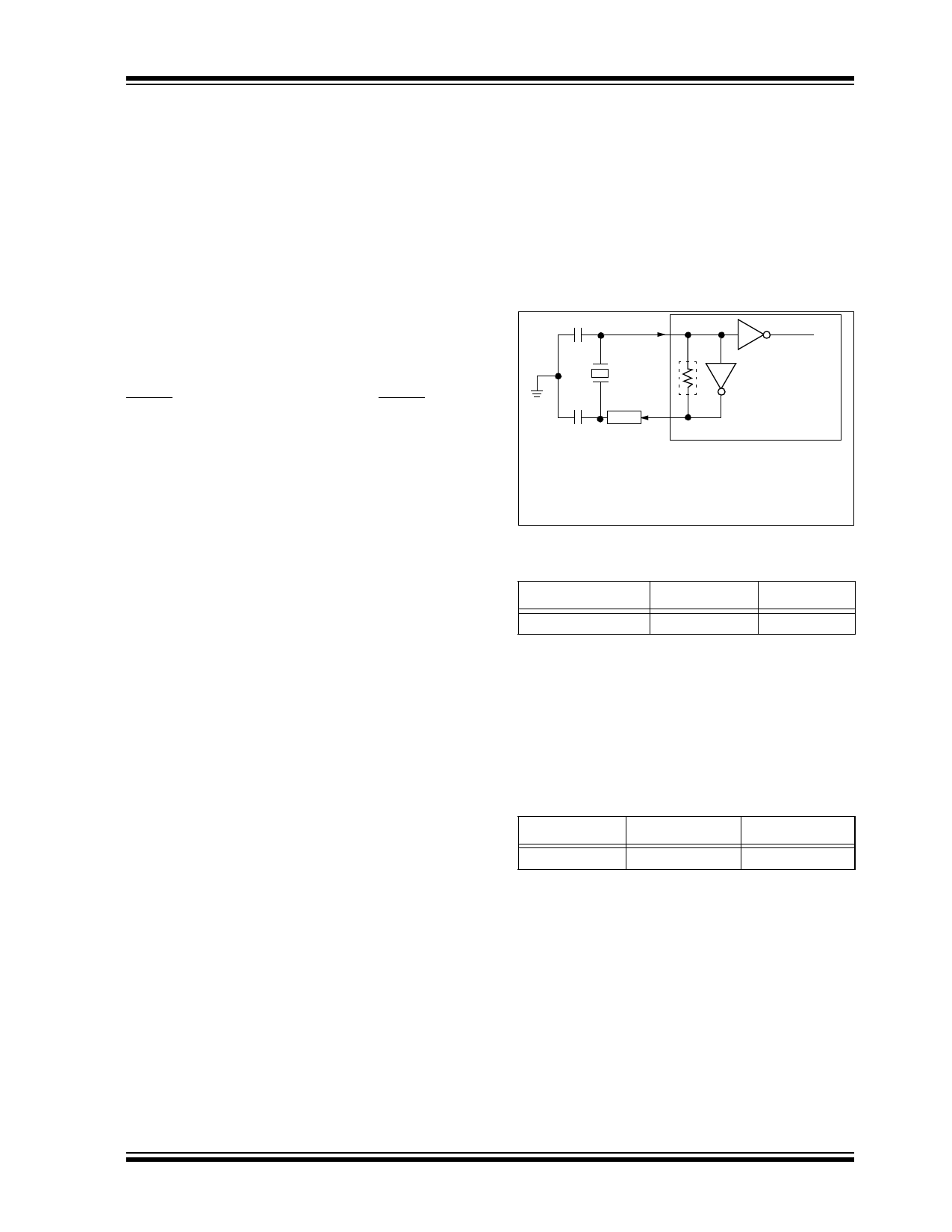
A crystal or ceramic resonator can be connected to the
OSC1 and OSC2 pins to establish oscillation
(Figure 2-1). The MCP2140 oscillator design requires
the use of a parallel-cut crystal. Use of a series of cut
crystals may give a frequency outside of the crystal
manufacturers specifications.
FIGURE 2-1:
C1
CRYSTAL OPERATION
(CERAMIC RESONATOR)
OSC1
To internal
logic
XTAL
OSC2
RS
C2 (Note)
RF
MCP2140
See Table 2-1 and Table 2-2 for recommended
values of C1 and C2.
Note: A series resistor may be required for
AT strip cut crystals.
TABLE 2-1: CAPACITOR SELECTION FOR
CERAMIC RESONATORS
Freq
OSC1 (C1) OSC2 (C2)
7.3728 MHz
10 - 22 pF
10 - 22 pF
Note:
Higher capacitance increases the stability
of the oscillator, but also increases the
start-up time. These values are for design
guidance only. Since each resonator has its
own characteristics, the user should consult
the resonator manufacturer for appropriate
values of external components.
TABLE 2-2:
Freq
CAPACITOR SELECTION FOR
CRYSTAL OSCILLATOR
OSC1 (C1)
OSC2 (C2)
7.3728 MHz
15 - 30 pF
15 - 30 pF
Note:
Higher capacitance increases the stability
of the oscillator but also increases the start-
up time. These values are for design guid-
ance only. RS may be required to avoid
overdriving crystals with low drive level
specification. Since each crystal has its
own characteristics, the user should con-
sult the crystal manufacturer for
appropriate values of external components.
2003 Microchip Technology Inc.
Preliminary
DS21790A-page 7
Share Link: