L6382D データシートの表示(PDF) - STMicroelectronics
部品番号
コンポーネント説明
一致するリスト
L6382D Datasheet PDF : 21 Pages
| |||
Application information
6
Application information
L6382D
6.1
Power management
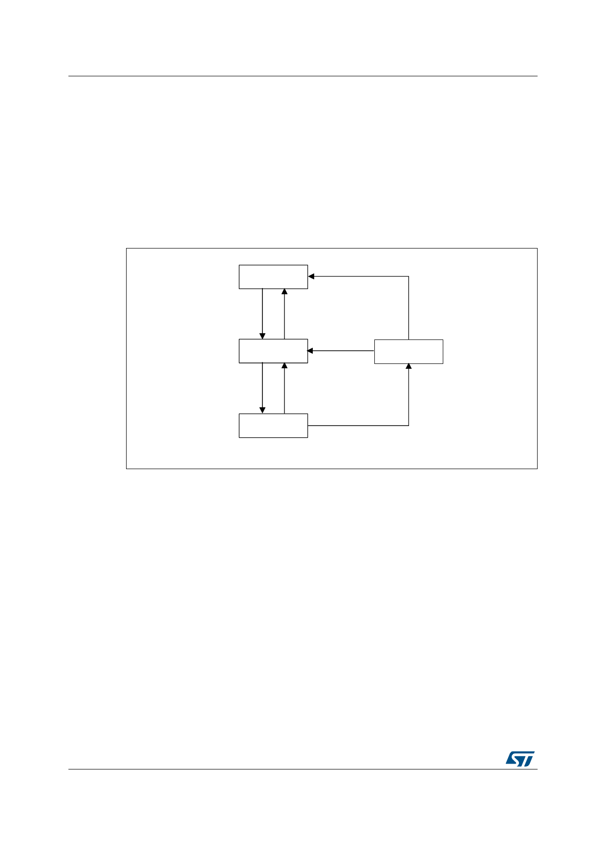
The L6382D has two stable states (save mode and operating mode) and two additional
states that manage the startup and fault conditions (Figure 10): the overcurrent protection is
a parallel asynchronous process enabled when in operating mode.
The following paragraphs describe each mode and the condition necessary to shift between
them.
Figure 10. State diagram
6.2
67$5783
9&& 95()
2))
9&&!9&&
21
9&& 95()
2))
6$9 (02'(
9&& 9&&
21
6+87'2:1
95()!9
7('!V
/*,ORZ
IRUPRUH
WKDQV
23(5$ 7,1*
02'(
9&& 9&&
2))
RU
95() 9
$09
Startup mode
With reference to the timing diagram in Figure 11, when power is first applied to the
converter, the voltage on the bulk capacitor builds up and the HV generator is enabled to
operate, drawing about 10 mA. This current, diminished by the IC consumption (less than
150 A), charges the bypass capacitor connected between pin Vcc and ground and makes
its voltage rise almost linearly.
During this phase, all IC functions are disabled except for:
the current sinking circuit on the VREF pin maintains the voltage low by keeping the
microcontroller connected to this pin disabled;
the high voltage startup (HVSU) that is ON (conductive) to charge the external
capacitor on pin Vcc.
12/21
DocID10972 Rev 8
Share Link: 