EM78P569 データシートの表示(PDF) - ELAN Microelectronics
部品番号
コンポーネント説明
一致するリスト
EM78P569 Datasheet PDF : 58 Pages
| |||
EM78P569
8-bit OTP Micro-controller
I. General Description
The EM78P569 is an 8-bit RISC type microprocessor with low power, high speed CMOS technology. There are
16Kx13 bits Electrical One Time Programmable Read Only Memory (OTP-ROM) within it. It provides security bits and
some One time programmable Option bits to protect the OTP memory code from any external access as well as to meet
user’s options.
This integrated single chip has an on_chip watchdog timer (WDT), program OTP-ROM, data RAM, LCD driver,
programmable real time clock/counter, internal interrupt, power down mode, built-in three-wire SPI, dual PWM(Pulse
Width Modulation), 6-channel 10-bit A/D converter, 10-bit D/A converter and tri-state I/O.
II. Feature
CPU
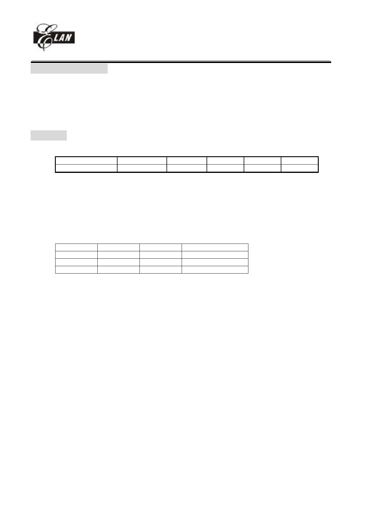
•Operating voltage : 2.2V~5.5V at main CLK less then 3.58MHz.
Main CLK(Hz)
Under 3.58M
7.16M
10.74M
14.4M
17.9M
Operating Voltage(min)
2.2
2.5
3
3.6
4V
•16k x 13 on chip Electrical One Time Programmable Read Only Memory (OTP-ROM)
•1k x 8 on chip data RAM
•Up to 51 bi-directional tri-state I/O ports
•16 level stack for subroutine nesting
•8-bit real time clock/counter (TCC)
•two 8-bit counters : COUNTER1 and COUNTER2
•On-chip watchdog timer (WDT)
•99.9% single instruction cycle commands
•8 level Normal mode frequency : 447.8K , 895.7K , 1.79M , 3.58M , 7.16M , 10.75M , 14.3M and 17.9M Hz.
Mode
CPU status Main clock 32.768kHz clock status
Sleep mode Turn off
Turn off
Turn off
Green mode Turn on
Turn off
Turn on
Normal mode Turn on
•Input port interrupt function
Turn on
Turn on
•12 interrupt source, 4 external, 8 internal
•Dual clocks operation (Internal PLL main clock , External 32.768KHz)
•8x8 accumulated multiplication-addition multiplier with sign and address auto-increment function
SPI
•Serial Peripheral Interface (SPI) : a kind of serial I/O interface
•Interrupt flag available for the read buffer full,
•Programmable baud rates of communication
•Three-wire synchronous communication. (shared with IO)
PWM
•Dual PWM (Pulse Width Modulation) with 10-bit resolution
•Programmable period (or baud rate)
•Programmable duty cycle
ADC
•Operating : 2.5V∼5.5V
•6-channel 10-bit successive approximation A/D converter
•Internal (VDD) or external reference
DAC
•Operating : 2.5V∼5.5V under VDD reference, 2.8V ~ 5.5V under 2.5V reference
•10-bit R-2R D/A converter
•Internal (VDD or 2.5V) reference
POR
•2.0V Power-on reset
__________________________________________________________________________________________________________________________________________________________________
* This specification is subject to be changed without notice.
1
8/19/2004 V4.4
Share Link: 