ACT6305 データシートの表示(PDF) - Active-Semi, Inc
部品番号
コンポーネント説明
一致するリスト
ACT6305 Datasheet PDF : 10 Pages
| |||
ACT6305
Rev 3, 15-Nov-12
APPLICATIONS INFORMATION
Output Voltage Selection
The ACT6305 provides fixed output voltage options
of 3.3V or 5V, or the output voltage may be ad-
justed over a 2V to 5V range by connecting an
external resistive voltage divider. When Output Volt-
age is set by external resistive voltage divider, add
a 47pF to 150pFcapacitor as feedforward capacitor
(CFF) as shown in Figure 1.
Table 1:
Output Voltage Programming
FB = OUT
FB = G
FB connect to resistive
divider
VOUT = 3.3V
VOUT = 5V
VOUT = 1.18V (1 + RFB1/RFB2)
Board Layout
To reduce noise and increase efficiency, high cur-
rent traces should be wide and direct, and an ex-
tended ground plane should be used. Switching
current paths should be laid out as tightly as possi-
ble, with the inductor and input and output capaci-
tors located close to the IC in order to reduce elec-
tromagnetic radiation.
If an external resistor divider is used, place the re-
sistors very close to the FB and G pins, and keep
them away from the high switching current paths.
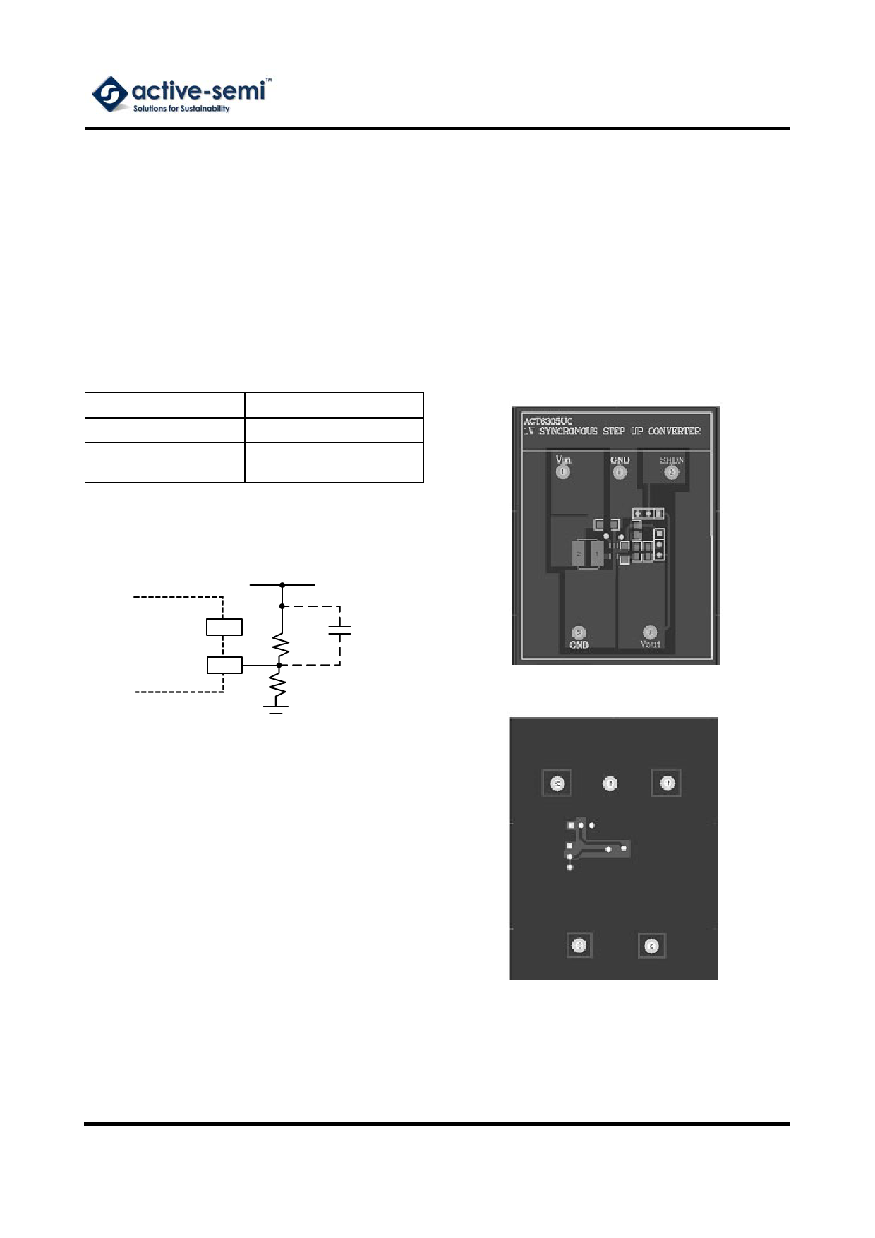
Figure 1:
Output Voltage Setting
VOUT
OUT
ACT6305
FB
RFB1
RFB2
CFF
Output Capacitor Selection
A minimum value of output capacitance is required
to maintain loop stability and normal operation of
the IC. The output capacitor value should be in the
range of 22µF to 100µF. To obtain small output rip-
ple, use a large capacitor with low ESR. Ceramic
capacitors should be used for highest performance.
If a tantalum capacitor is used, choose only low
ESR types and a smaller low ESR capacitor of
about 1µF can be connected in parallel to filter high
frequency noise.
Inductor Selection
For most applications, the inductor value should be
in the range of 4.7µH to 22µH. Smaller inductors
provide faster load transient response and have a
smaller physical size, but they also result in higher
ripple current and reduce the maximum available
output current. Choose inductors with low series
resistance to obtain the highest efficiency.
Innovative PowerTM
-8-
www.active-semi.com
Copyright © 2012 Active-Semi, Inc.
Share Link: 