IMSB300 データシートの表示(PDF) - STMicroelectronics
部品番号
コンポーネント説明
一致するリスト
IMSB300 Datasheet PDF : 12 Pages
| |||
IMS B300 Ethernet connection system datasheet
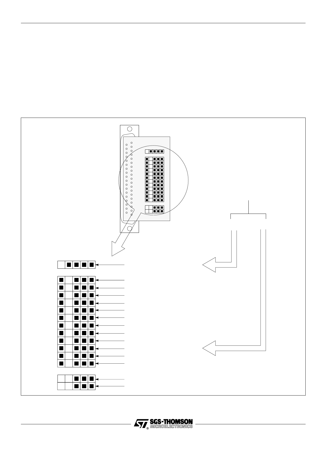
3.2.1 Connections to an IMS B014
The use of the IMS CA16 cable in conjunction with the connectors on a IMS B014 standard VME motherboard is illustrated
in figure 4. The jumper configuration of the motherboard is shown in figure 4. As can be seen, the single ended cable
connections from the IMS B300 are mated with a ‘breakout’ connector or ‘hedgehog’ mounted in the P4 front panel con-
nector of the IMS B014. A TRAM should be inserted in slot 0 of the IMS B014 motherboard array. Other TRAMs may
be added to the motherboard as required. The IMS B014 can be inserted in a VME rack or used in a bench-top mode
via a separate power supply.
Note that this example assumes the use of a 20Mbit/s link speed on both the IMS B300 subsystem and the IMS B014
motherboard. Also note that it is not possible to configure an IMS B014 to access the appropriate signal connections via
its back panel (P2) connector.
From IMS B300
via IMS CA16 cable
SubsystemDown
Link
FrontServicesUp (on P4)
Link 0
Link 1
Link 2
Link 3
Link 4
Link 5
Link 6
Link 7
FrontConfigUp (on P4)
Connector Link (on P4)
not used
FrontConfigDown (P5)
not used
FrontServicesDown (on P5)
Figure 4 Front panel ‘breakout’ connector on P4 of IMS B014
5/12
Share Link: 