VSC7173XYI/G24 データシートの表示(PDF) - Maxim Integrated
部品番号
コンポーネント説明
一致するリスト
VSC7173XYI/G24
Maxim Integrated

VSC7173XYI/G24 Datasheet PDF : 17 Pages
| |||
VSC7173
Data Sheet
FUNCTIONAL DESCRIPTIONS
Modes of Operation
Table 1 summarizes the VSC7173 operational mode choices. The mode of the VSC7173 is determined by the
following pins.
MODE1: Controls whether the selection of port 0 to port 1 is edge-sensitive or level-sensitive. When LOW, port
selection is level-sensitive (to enable level-sensitive port selection, pin PORTSEL1 must also be LOW). When HIGH,
port selection is edge-sensitive.
MODE0: Controls the function of the unselected port. When LOW, the output of this port is turned off. When HIGH,
the output of this unselected port is the same data as seen on the selected port.
PORTSEL0: In level-sensitive mode (MODE1 is LOW and PORTSEL1 is LOW), controls the selection of port 0 or
port 1. When LOW, port 0 is selected; when HIGH, port 1 is selected. In edge-sensitive mode (MODE1 is HIGH),
controls the selection of port 0; a rising edge on this pin selects port 0.
PORTSEL1: In level-sensitive mode (MODE1 is LOW), must be held LOW. In edge-sensitive mode (MODE1 is
HIGH), controls the selection of port 1; a rising edge on this pin selects port 1.
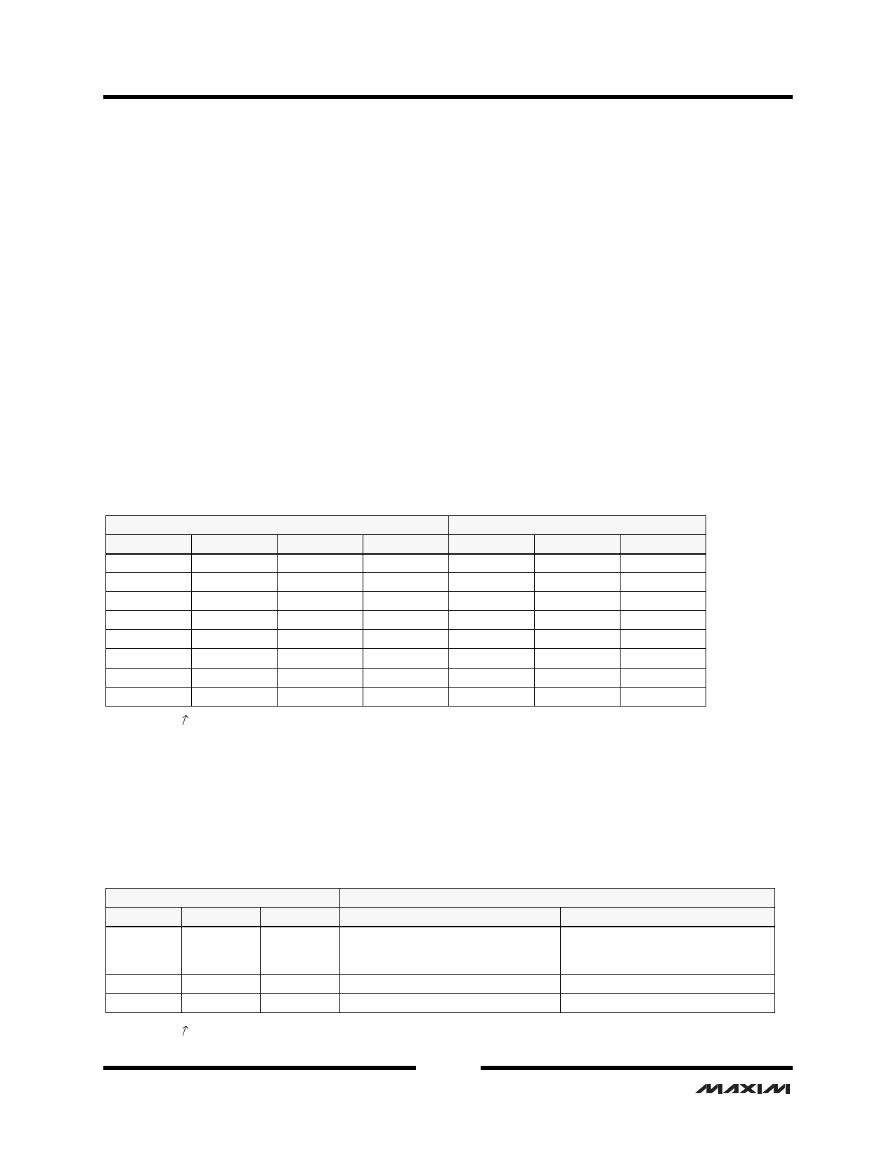
Table 1. Port Selection Operating Modes
MODE1
0 (level)
0 (level)
0 (level)
0 (level)
1 (edge)
1 (edge)
1 (edge)
1 (edge)
Input Pins
MODE0
PORTSEL0
0
0
0
1
1
0
1
1
0
X
0
↑
1
X
1
↑
PORTSEL1
0
0
0
0
↑
X
↑
X
X = don’t care; ↑ = rising.
High-Speed Connections
P0OUT
P1OUT
P2OUT
P2IN
OFF
P0IN
OFF
P2IN
P1IN
P2IN
P2IN
P0IN
P2IN
P2IN
P1IN
OFF
P2IN
P1IN
P2IN
OFF
P0IN
P2IN
P2IN
P1IN
P2IN
P2IN
P0IN
Status Pins
Two output pins, P0SLTD and OOBPORT0, are provided for status monitoring. Table 2 summarizes the functionality
of these two output pins. OOBPORT0 reports whether the signal on port 0 is above or below the threshold selected in
Table 5. P0SLTD, depending on the state of MODE1, can either report which port is selected or can report whether
the signal on port 1 is above or below the threshold selected in Table 5.
Table 2. Output Status Pins
MODE1
0 (level)
1 (edge)
1 (edge)
Input Pins
PORTSEL0
X
X
↑
PORTSEL1
X
↑
X
Output Status Pins
P0SLTD
OOBPORT0
OOB status port 1—1 indicates signal is OOB status port 0—1 indicates signal
below OOB threshold, 0 indicates signal is below OOB threshold, 0 indicates
is above OOB threshold
signal is above OOB threshold
Indicates port selected, 0 = port 1
OOB status port 0
Indicates port selected, 1 = port 0
OOB status port 0
X = don’t care; ↑ = rising.
Revision 4.1
May 23, 2005
4 of 17
Confidential
Share Link: