L6232E データシートの表示(PDF) - STMicroelectronics
部品番号
コンポーネント説明
一致するリスト
L6232E Datasheet PDF : 10 Pages
| |||
L6232E
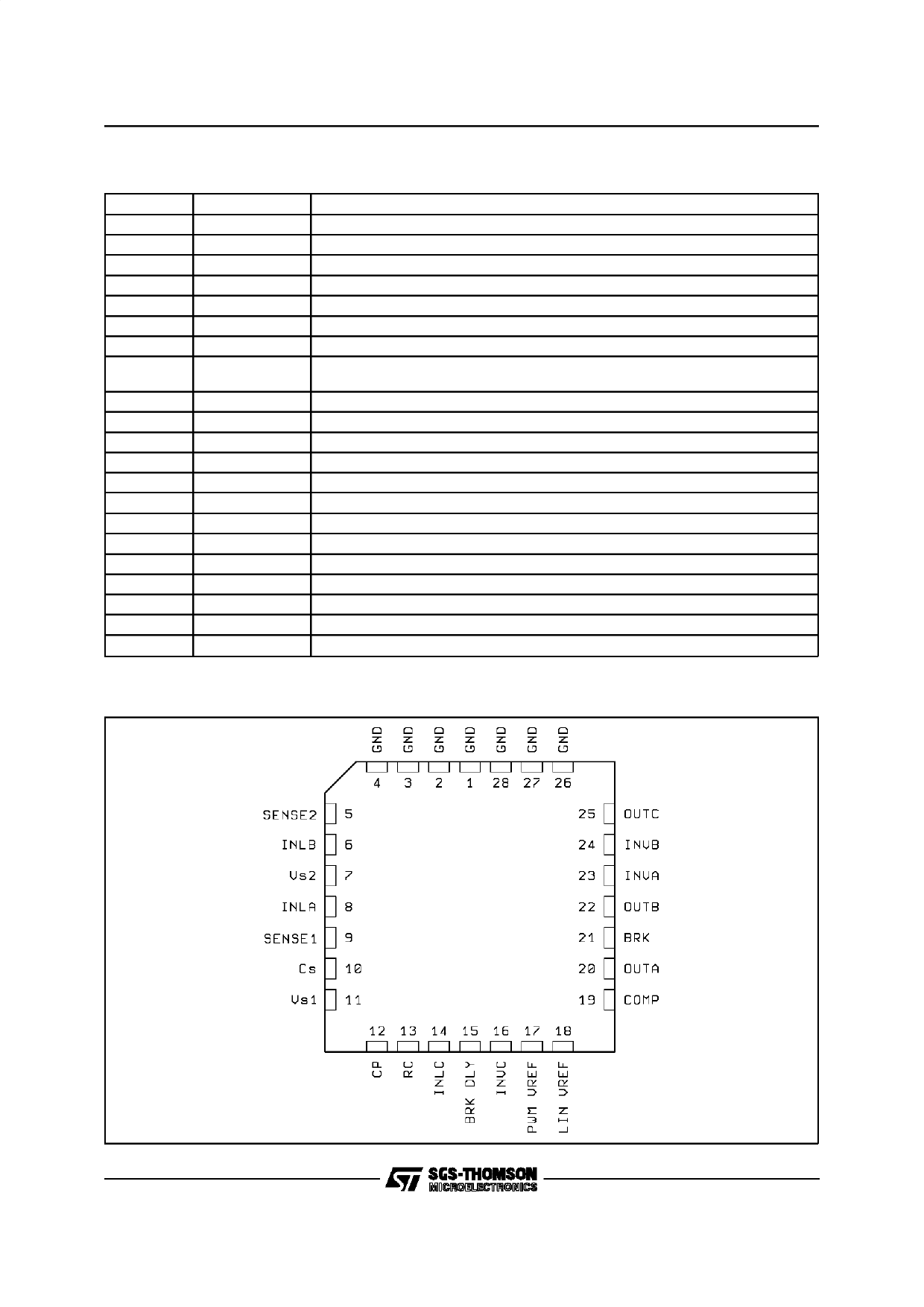
PIN DESCRIPTION
Pin
1 to 4
5, 9
6
7, 11
8
10
12
13
Name
GND
SENSE
INLB
VS
INLA
CS
CP
RC
14
15
16
17
18
19
20
21
22
23
24
25
26 to 28
INLC
BRK DLY
INUC
PWM Vref
LIN Vref
COMP
OUTA
BRK
OUTB
INUA
INUB
OUTC
GND
Function
Common Ground. Also provides heat-sink to PCB.
Output for current sense resistors.
Logic Input to turn on the lower driver (Active High).
Supply Voltage.
Logic input to turn on the lowey driver (Active High).
External Charge Pump Capacitor.
External Main Charge Pump capacitor.
Cutoff Time RC Network in PWM mode. The Resistor value is also used to define
the slew-rate in linear mode (LIN).
Logic input to turn on the lower driver (Active High).
External RC network for the brake delay.
Logic Input to turn on the upper driver (Active Low).
Input for Reference Control in PWM mode
Input for Reference Control voltage in LIN mode
External compensation for error amplifier
DMOS Half-bridge A Out.
Active LOW logic input that triggers the delayed brake.
DMOS Half-bridge B Out.
Logic Input to turn on the upper drivers (Active Low).
Logic Input to turn on the upper drivers (Active Low).
DMOS Half-bridge C Out.
Common Ground. Also provides heat-sink to PCB.
PIN CONNECTION (Top view)
2/10
Share Link: 