T7264 データシートの表示(PDF) - Agere -> LSI Corporation
部品番号
コンポーネント説明
一致するリスト
T7264 Datasheet PDF : 54 Pages
| |||
Data Sheet
April 1998
T7264 U-Interface 2B1Q Transceiver
Functional Overview (continued)
Device Interface and Connections
The device provides rapid cold start and warm start op-
eration. From a cold start, the device is typically opera-
tional within 3.5 s. The device supports activation/
deactivation, and, when properly deactivated, it stores
the adaptive filter coefficients such that upon the next
activation request, a faster warm start is possible. A
warm start typically requires 200 ms for the device to be-
come operational.
The T7264 has an on-chip activation/deactivation state
machine and timers, and automatically moves from
state T0 to T7 (as specified in the T1.601 standard) dur-
ing activation. This simplifies the implementation of the
T1.601 (Appendix C) state table. The signals from the
device control and status octets on the K2 interface pro-
vide the control necessary to complete the state table.
The activation/deactivation process is controlled over
the K2 interface.
The T7264 has a low-power mode which it automatically
enters when it is in the idle state. The idle state occurs
after deactivation, loss of sync on the U-interface, or re-
leasing reset. In the low-power mode, power consump-
tion is typically 30 mW.
The T7264 transceiver allows systems to meet the
loop-range requirements of ANSI Standard T1.601
when the transceiver is used with the proper peripheral
circuitry. Devices achieve better than 10–7 bit error rate
over 18 kft of 26 AWG loop cable.
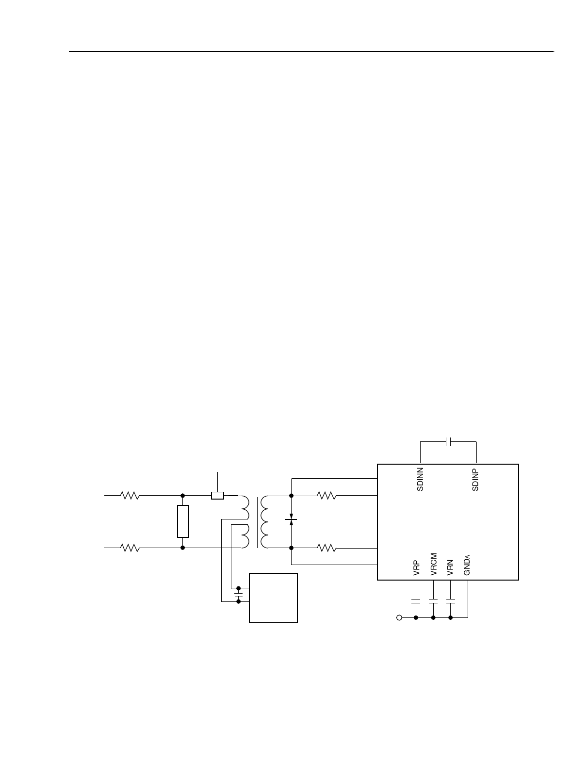
Analog Device Interface
Proper line termination is required, utilizing appropriate
interface components, to meet the 2.5 V pulse tem-
plate. The output of the T7264 should first pass through
a pair of 16.9 Ω resistors and into a 1.5:1 ratio trans-
former, such as the Lucent 2754H (or the short-lead
version 2754H2). The output of the transformer is cou-
pled through a 1.0 µF capacitor, is passed through a
pair of 16.9 Ω resistors, and then drives the 135 Ω line.
Surge protection circuitry is necessary on each side of
the transformer when the U loop is external to a build-
ing. The protection between the 16.9 Ω resistors and
the transformer should be a Lucent 521A surge protec-
tor or equivalent. A relay may be needed to disconnect
the loop plant for local loopback testing. Figure 4 shows
a recommended circuit for interfacing the T7264 to the
line; however, the specific interface is system depen-
dent.
820 pF ± 5%
16.9 Ω ± 7%
SURGE
PROTECTION
16.9 Ω ± 7%
LOOPBACK
RELAY
2754H
1.5:1
7
1
10
6
9
5
16.9 Ω ± 1%
521A
SURGE
PROTECTION
16.9 Ω ± 1%
1.0 µF
LUCENT
701C
dc
REMOTE
POWER
SOURCE
36 HP
32 LOP
37
38
T7264
35 LON
31 HN
29 28 30 24
0.1 µF
GNDA
5-5803Fa
Note: 3000 pF ± 1% capacitors from HP and HN to GNDA may improve operation of the tone decoder in the presence of interfering common-
mode signals.
Figure 4. Line Interface and Protection
Lucent Technologies Inc.
7
Share Link: 