CMX631A データシートの表示(PDF) - MX-COM Inc
部品番号
コンポーネント説明
一致するリスト
CMX631A Datasheet PDF : 12 Pages
| |||
Low Voltage SPM Detector
6
CMX631A PRELIMINARY INFORMATION
4 General Description
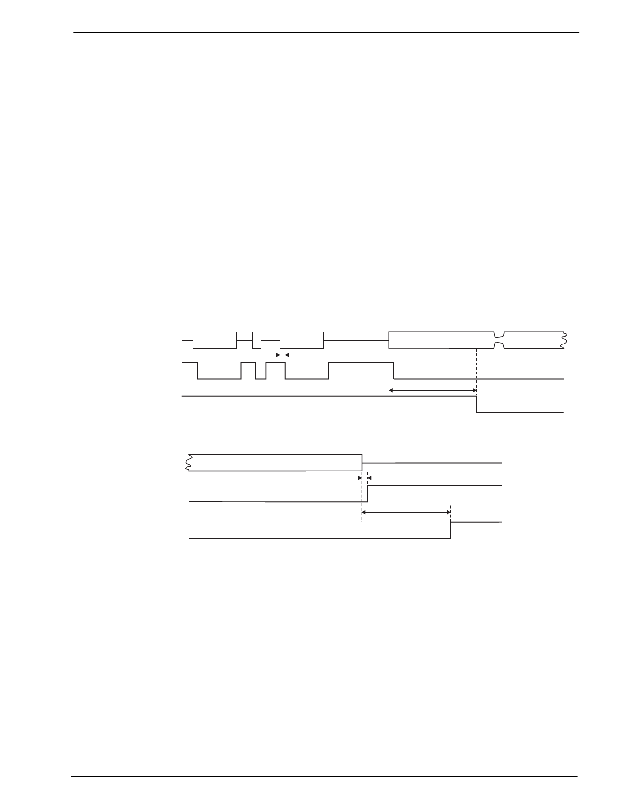
4.1 Tone Follower Mode
The Tone Follower Output Mode will respond and/or de-respond when a signal is detected or a NOTONE, by
providing a Logic level output. When a signal has been detected, a Logic 0 is provided at the output for the
duration of the valid signal. When a NOTONE or invalid decode is detected a Logic 1 is provided at the
output until a valid signal is available. See Figure 3.
4.2 Packet Mode
The Packet (Cumulative Tone) Mode Output will respond and/or de-respond after a cumulative 40ms of good
tone (or NOTONE) in any 48ms period by providing a Logic level output. See Figure 3.
This process does ignore the small fluctuations or fades of a valid frequency input. During a 40ms toneburst,
no tone interruption (small fluctuation or fade) is allowed during this period for the signal to be considered
valid. If a 45ms toneburst occurs, then a 2ms interruption is allowed, and the signal is still considered valid.
For NOTONE, there must be 40ms of continuous no tone or for a 45ms period, there may be 2ms of tone and
the NOTONE still be valid. For a valid detect of tone the output provides a Logic 0. For the valid detect of
NOTONE, the output provides a Logic 1.
This output is available for µProcessor ‘Wake-Up’, Minimum Tone detection, NOTONE indication, or transient
avoidance.
SIGNAL INPUT
TONE FOLLOWER OUTPUT
PACKET MODE OUTPUT
Response
RESPONSE DELAY
RESPONSE DELAY
SIGNAL INPUT
TONE FOLLOWER OUTPUT
PACKET MODE OUTPUT
De-response
DERESPONSE DELAY
DERESPONSE DELAY
Figure 3: Tone Follower and Packet Mode Outputs
4.3 Sensitivity Setting
The CMX631A input sensitivity can be accurately adjusted and set to support many national 12kHz and
16kHz SPM specifications.
4.3.1 Input Gain Calculation
The input amplifier, with external circuitry, is used to set the sensitivity of the CMX631A to conform to the
user's national level specification with regard to ‘Must’ and ‘Must-Not’ decode signal levels.
With reference to the graphs in Figure 4 and Figure 5, the following steps will assist in the determination of the
required gain/attenuation.
1. Draw two horizontal lines from the Y-axis [Signal Level (dB)] in Figure 4 and Figure 5. The upper line
represents the required ‘Must’ decode level. The lower line represents the required ‘Must-Not’ decode
level
© 1999 MX•COM Inc.
www.mxcom.com Tele: 800 638-5577 336 744-5050 Fax: 336 744-5054
Doc. # 20480177.004
4800 Bethania Station Road, Winston-Salem, NC 27105-1201 USA All trademarks and service marks are held by their respective companies.
Share Link: 