MAX6603 データシートの表示(PDF) - Maxim Integrated
部品番号
コンポーネント説明
一致するリスト
MAX6603 Datasheet PDF : 9 Pages
| |||
Dual-Channel, Platinum RTD-to-Voltage
Signal Conditioner
ABSOLUTE MAXIMUM RATINGS
(All voltages referenced to GND, unless otherwise noted.)
VCC ........................................................................-0.3V to +6.0V
RS1+, RS1-, RS2+, RS2- .....................................-0.3V to +18.0V
OUT1, OUT2, DG1, DG2 ............................-0.3V to (VCC + 0.3V)
Continuous Power Dissipation (TA = +70°C)
10-Pin TDFN Single-Layer Board
(derate 18.5 mW/°C above +70°C) .........................1481.5mW
10-Pin TDFN Multilayer Board
(derate 24.4 mW/°C above +70°C) .........................1951.2mW
ESD Protection (OUT1, OUT2, DG1, DG2,
Human Body Model) .....................................................> ±2kV
ESD Protection (RS1+, RS2+, RS1-, RS2-,
VCC, GND, Human Body Model) ..................................> ±5kV
Operating Temperature Range .........................-40°C to +125°C
Junction Temperature ......................................................+150°C
Storage Temperature Range .............................-65°C to +150°C
Lead Temperature (soldering, 10s) .................................+300°C
Stresses beyond those listed under “Absolute Maximum Ratings” may cause permanent damage to the device. These are stress ratings only, and functional
operation of the device at these or any other conditions beyond those indicated in the operational sections of the specifications is not implied. Exposure to
absolute maximum rating conditions for extended periods may affect device reliability.
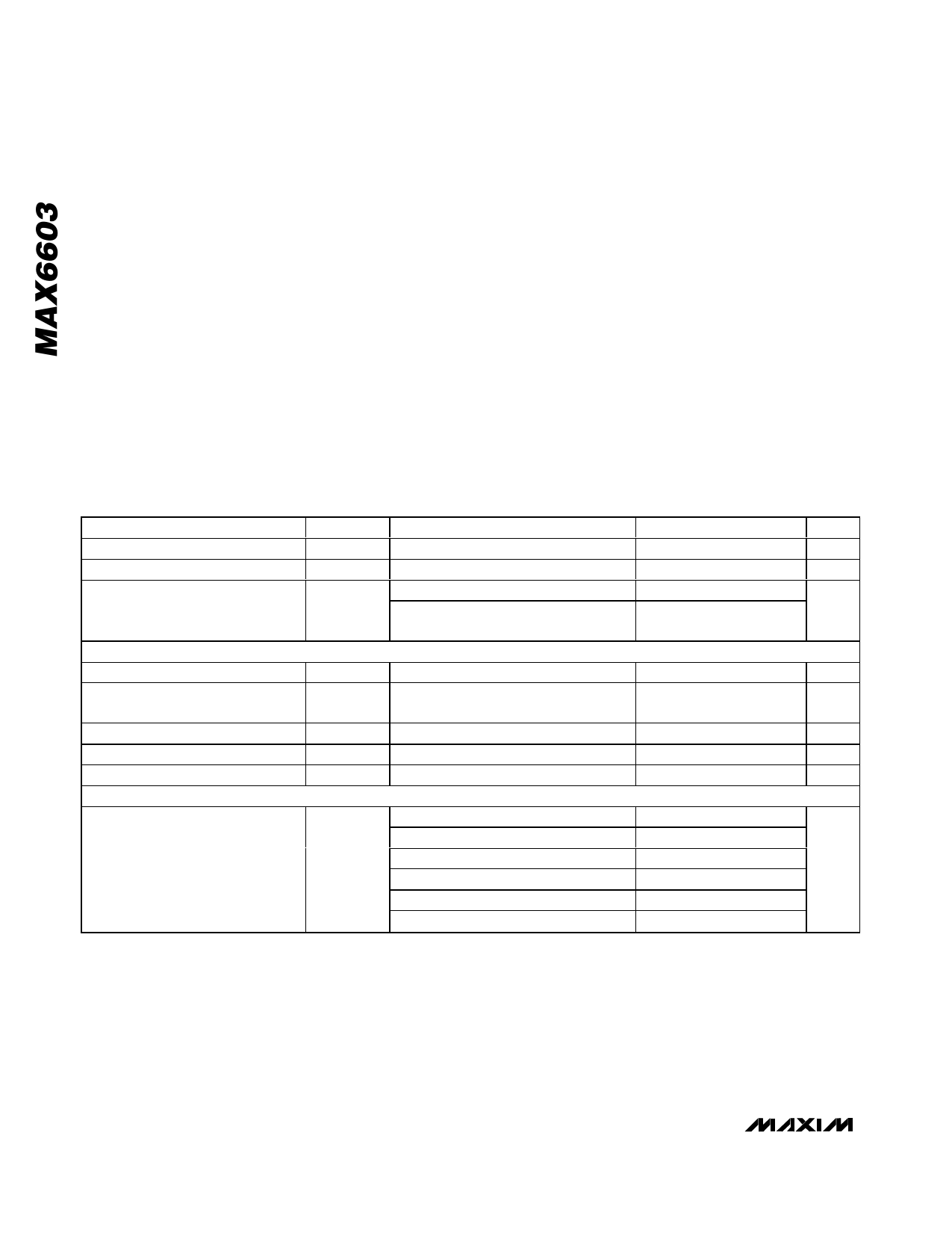
ELECTRICAL CHARACTERISTICS
(VCC = 3.0V to 5.5V, resistor connected between RS1+ and RS1- = 560Ω, resistor connected between RS2+ and RS2- = 560Ω,
TA = -40°C to +125°C, unless otherwise noted. Typical values are at VCC = 5.0V, RL = 47kΩ between OUT_ and GND, TA = +25°C.)
(Note 1)
PARAMETER
SYMBOL
CONDITIONS
MIN
Supply Voltage
VCC
3.0
Input Over Voltage
VRS
RS1+, RS1-, RS2+, RS2-
Supply Current
ICC
Sink current during overvoltage fault
VRS1+ = VRS1 - = VRS2+ = VRS2- = +16V
CURRENT SOURCES
Excitation Current
IEXC
(Note 2)
0.58
Excitation-Current Temperature
Coefficient
TCIEXC (Note 2)
Minimum RS_- Voltage
VRS_-
Maximum RS_+ Voltage
VRS_+
Supply Ratiometric
IRATIO
MAXIMUM TEMPERATURE ERROR (Note 3)
VCC = +3V to +5.5V
RTD
+400°C to +600°C, VCC = 5.0V
-40°C to +400°C, VCC = 5.0V
+600°C to +1000°C, VCC = 5.0V
+400°C to +600°C, VCC = 3.0V
-40°C to +400°C, VCC = 3.0V
+600°C to +1000°C, VCC = 3.0V
TYP MAX UNITS
5.5
V
16
V
3.9
5.5
mA
36.2 47.1
1.0
1.12
mA
-7
ppm/°C
3.4
V
4.0
V
0.2
mA/V
±6
±8
±12
°C
±10
±13.3
±20
2 _______________________________________________________________________________________
Share Link: 