HMC262(2001) データシートの表示(PDF) - Hittite Microwave
部品番号
コンポーネント説明
一致するリスト
HMC262 Datasheet PDF : 6 Pages
| |||
MICROWAVE CORPORATION
HMC262
FEBRUARY 2001
HMC262 LOW NOISE AMPLIFIER 15 - 24 GHz
V01.05.00
MIC Assembly Techniques for HMC262
1
Mounting & Bonding Techniques for Millimeterwave GaAs MMICs
The die should be attached directly to the ground plane eutectically or
with conductive epoxy (see HMC general Handling, Mounting, Bond-
ing Note).
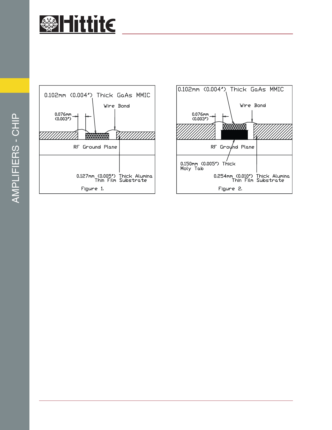
50 Ohm Microstrip transmission lines on 0.127mm (5 mil) thick alumina
thin film substrates are recommended for bringing RF to and from the
chip (Figure 1). If 0.254mm (10 mil) thick alumina thin film substrates
must be used, the die should be raised 0.150mm (6 mils) so that the
surface of the die is coplanar with the surface of the substrate. One way
to accomplish this is to attach the 0.102mm (4 mil) thick die to a
0.150mm (6 mil) thick molybdenum heat spreader (moly-tab) which is
then attached to the ground plane (Figure 2).
Microstrip substrates should brought as close to the die as possible in
order to minimize bond wire length. Typical die-to-substrate spacing
is 0.076mm (3 mils).
Figure 3: Typical HMC262 Assembly
An RF bypass capacitor should be used on the Vdd input. A 100 pF single layer capacitor (mounted eutectically or by
conductive epoxy) placed no further than 0.762mm (30 Mils) from the chip is recommended. The photo in figure 3 shows
a typical assembly for the HMC262 MMIC chip.
12 Elizabeth Drive, Chelmsford, MA 01824 Phone: 978-250-3343
1 - 20
Fax: 978-250-3373
Web Site: www.hittite.com
Share Link: 