MTD800 データシートの表示(PDF) - Myson Century Inc
部品番号
コンポーネント説明
一致するリスト
MTD800 Datasheet PDF : 42 Pages
| |||
MYSON
TECHNOLOGY
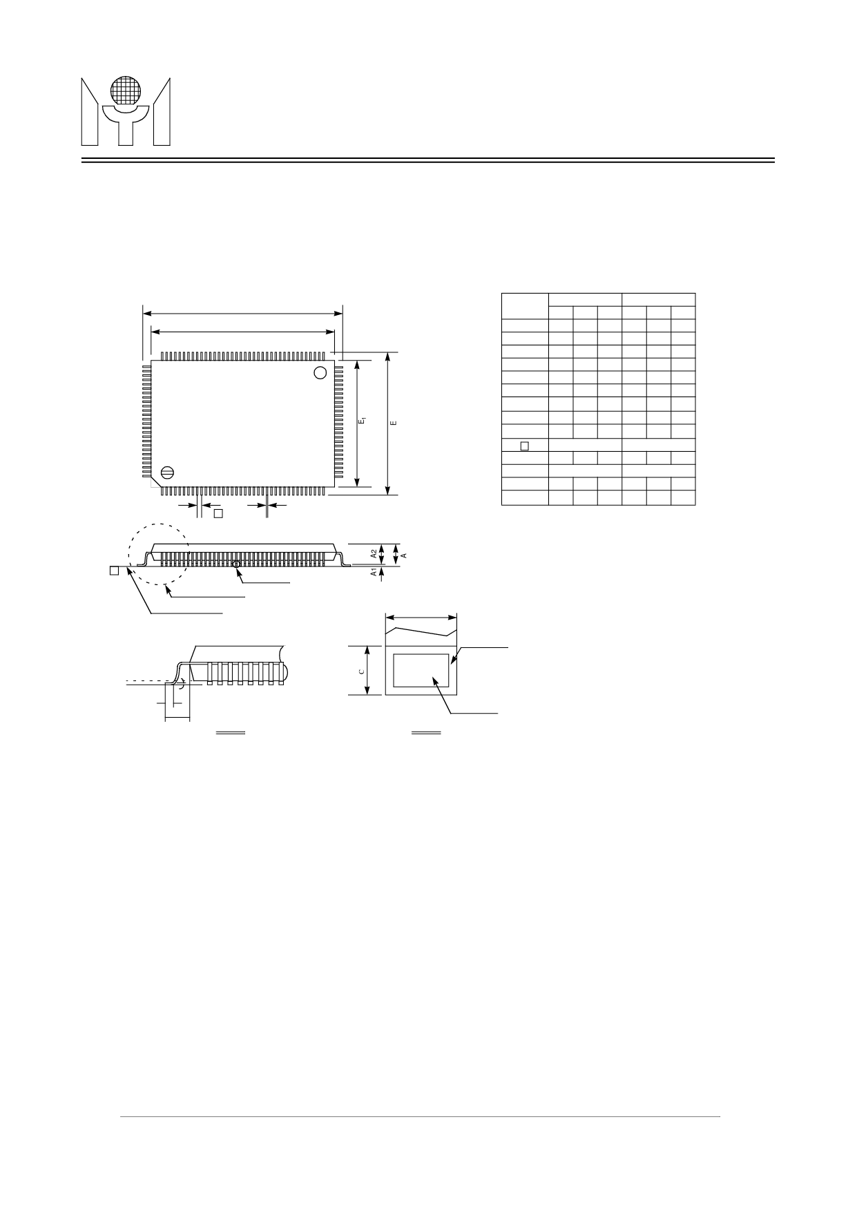
6.0 PACKAGE DIMENSION
6.1 128 pin PQFP
MTD 800
(Preliminary)
D1
D
102
103
65
64
128
1
e
39
38
B
y
See Detail B
See Detail A
Seating Plane
Gage Plane
z
L
L1
Detail A
Symbol
A
A1
A2
B
C
D
D1
E
E1
e
L
L1
y
z
Dimension in inch Dimension in mm
Min Norm Max Min Norm Max
-
- 0.134 -
- 3.40
0.010 -
- 0.25 -
-
0.107 0.112 0.117 2.73 2.85 2.97
0.007 0.009 0.011 0.17 0.22 0.27
0.004 - 0.008 0.09 - 0.20
0.906 0.913 0.921 23.00 23.20 23.40
0.783 0.787 0.791 19.90 20.00 20.10
0.669 0.677 0.685 17.00 17.20 17.40
0.547 0.551 0.555 13.90 14.00 14.10
0.020 BSC
0.50 BSC
0.029 0.035 0.041 0.73 0.88 1.03
0.063 BSC
1.60 BSC
-
- 0.004 -
- 0.10
0o
-
7o
0o
-
7o
Note:
1.Dimension D1 & E1 do not include mold protrusion.
But mold mismatch is included. Allowable protrusion is .25mm/.010” per side.
2.Dimension B does not include dambar protrusion. Allowable dambar protru-
sion .08mm/.003”. Total in excess of the B dimemsion at maximum material
condition. Dambar cannot be located on the lower radius or the foot.
3.Controlling dimension : Millimeter.
B
With Plating
Detail B
Base Metal
42/42
MTD800 Revision 0.0 07/20/1999
Share Link: 