CA3256 データシートの表示(PDF) - Intersil
部品番号
コンポーネント説明
一致するリスト
CA3256 Datasheet PDF : 11 Pages
| |||
CA3256
buffer amplifier. The T-switch, together with the input
impedance of the buffer, is typically 10kΩ, and has an inser-
tion loss of approximately 0.8dB. The T-switch was designed
to handle up to 3VP-P input signal with low distortion. The
T-switches of the CA3256 conform to a break-before-make
format; hence, shorting to ground is eliminated.
The amplifier is programmable for gain and, typically, can
provide a gain of 1 into a 75Ω load or a gain of 5 into a 1kΩ
load. The maximum output signal swing with linearity is
greater than 5VP-P for (V+ to V-) greater than or equal to
12V, while the maximum output current is approximately
20mA. The amplifier has base-current compensation to
reduce offset and a temperature compensated 5V zener ref-
erenced bias. Other features include LED-selector indicators
for channels 1 through 4. The fifth channel is independently
selectable for use as a separate input or output in parallel
with any on channel, and may be used as a monitor, or for
pass-through, signal summing, or parallel distribution.
In the application, the user has the option to specify V- = -5V
for the switch and a ground reference for the amplifier input
and output. Alternatively, the CA3256 may be used with a
single +12V supply. The logic select for channels 1 through 4
is controlled by the A, B and Inhibit lines with ground to V+
logic switching. The logic threshold is approximately
(V+ - V-)/2 referenced to ground. DC coupling may also be
used at the output (when V- is returned to a -5V supply). For
the circuit of Figure 3, AC coupling is used at the output and
input. The switching bias arrangement shown provides for
stable bias across each switch when in the off position to
minimize transients when the input is switched.
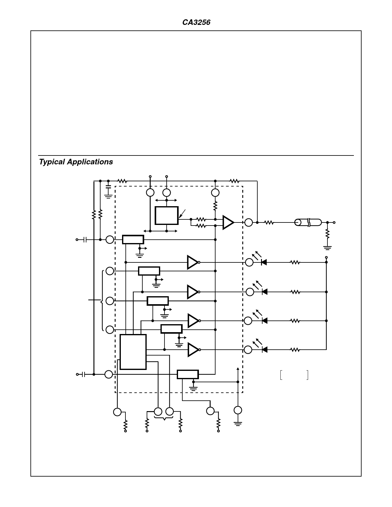
Typical Applications
V- V+
100K
-5V
+7V TO +12V
RF
100K
100K
CHANNEL 1
INPUT
15
17
5
14
BIAS
REG
TG-1
TG-2
V- +5V
10K
10K
1
8
1K
-
+
9
OUTPUT
AMP
12
AMPLIFIER
TO CABLE
OUTPUT
OUT
75Ω
75Ω
LED INDICATOR CHANNEL 1
VLED
LED INDICATOR CHANNEL 2
2 OF 5
INPUTS
1
SHOWN
3
2
TG-3
3
TG-4
11
LED INDICATOR CHANNEL 3
10
CHANNEL 5
INPUT/
OUTPUT
LLC
ENABLE
AND
CHAN 1-4
SELECT
13
4
TG-5
LED INDICATOR CHANNEL 4
2
WHERE AMPLIFIER GAIN:
AV = 1 + R-----F-1----0+---K--1----K--- x0.9
i.e., FOR AV = 1.8
ENABLE
CHANNEL 6
1-4
4.7K
4.7K
AB
16 18
SELECT
CHANNEL
1-4
C
SELECT
CHANNEL 7
5
4.7K
4
4.7K
GND
RF = 9kΩ
FIGURE 2. TYPICAL APPLICATION WITH DIRECT-COUPLED OUTPUT AND V- = -5V (DIP PINOUT)
8-6
Share Link: 